
Inside the Physical AI Factory · Part 6 of 8
Industrial Automation Explained: PLCs, CNC Machines, Robots, Sensors, and Factory Software
A first principles guide to the factory control loop, sensors, actuators, motors, drives, PLCs, safety systems, CNC, robots, industrial networks, and the software that turns a production order into a physical product.
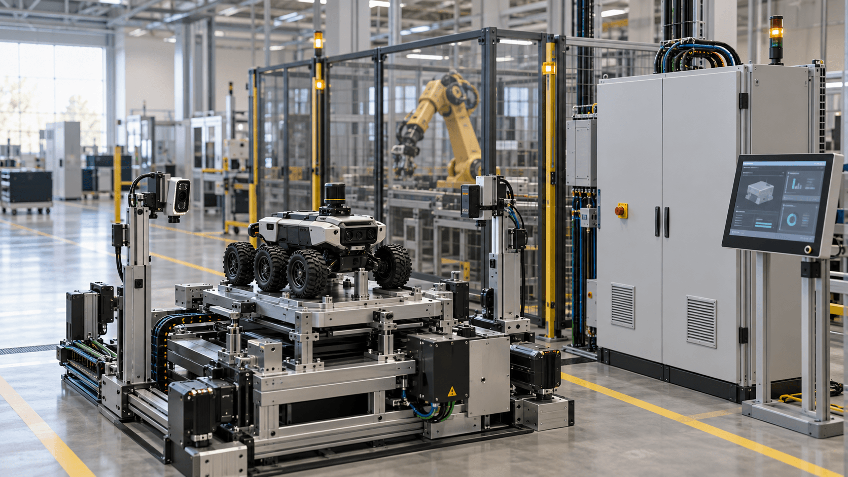
This is Part 6 of Inside the Physical AI Factory. Part 5 turned the rover production route into a plant. Now we open the factory nervous system: the devices and software that sense conditions, make decisions, create motion, protect people, coordinate work, and preserve evidence of what happened.
Industrial automation is easiest to understand from the machine outward. A sensor detects that a rover frame has reached a fixture. A controller evaluates the signal and the machine state. A drive regulates a motor. An actuator moves a clamp. A safety system watches a separate set of conditions. An operator interface explains what the cell is doing. Networks carry selected information to supervisory and production systems. The production record eventually receives the result.
The factory is not one computer with a large dashboard. It is a collection of control loops operating at different speeds, with different consequences, owners, and evidence requirements. A motion controller may update an axis far faster than an enterprise planning system needs to know that the work order has started. A safety function must reach a defined safe state without depending on a cloud service or a language model. A maintenance planner can tolerate minutes of delay that a servo loop cannot.
This report follows one illustrative rover production order from business planning to physical action and back into the production record. It also draws a boundary between conventional automation and physical AI. The goal is not to replace proven control. It is to see where perception, learning, planning, and adaptation can add value without weakening deterministic behavior, functional safety, traceability, or operating ownership.
The Short Answer
Industrial automation uses sensing, logic, communication, and controlled energy to make a physical process repeatable. Sensors measure the world. Controllers compare those measurements with commands and permitted states. Actuators, motors, valves, and other final elements change the process. Feedback tells the controller whether the expected result occurred.
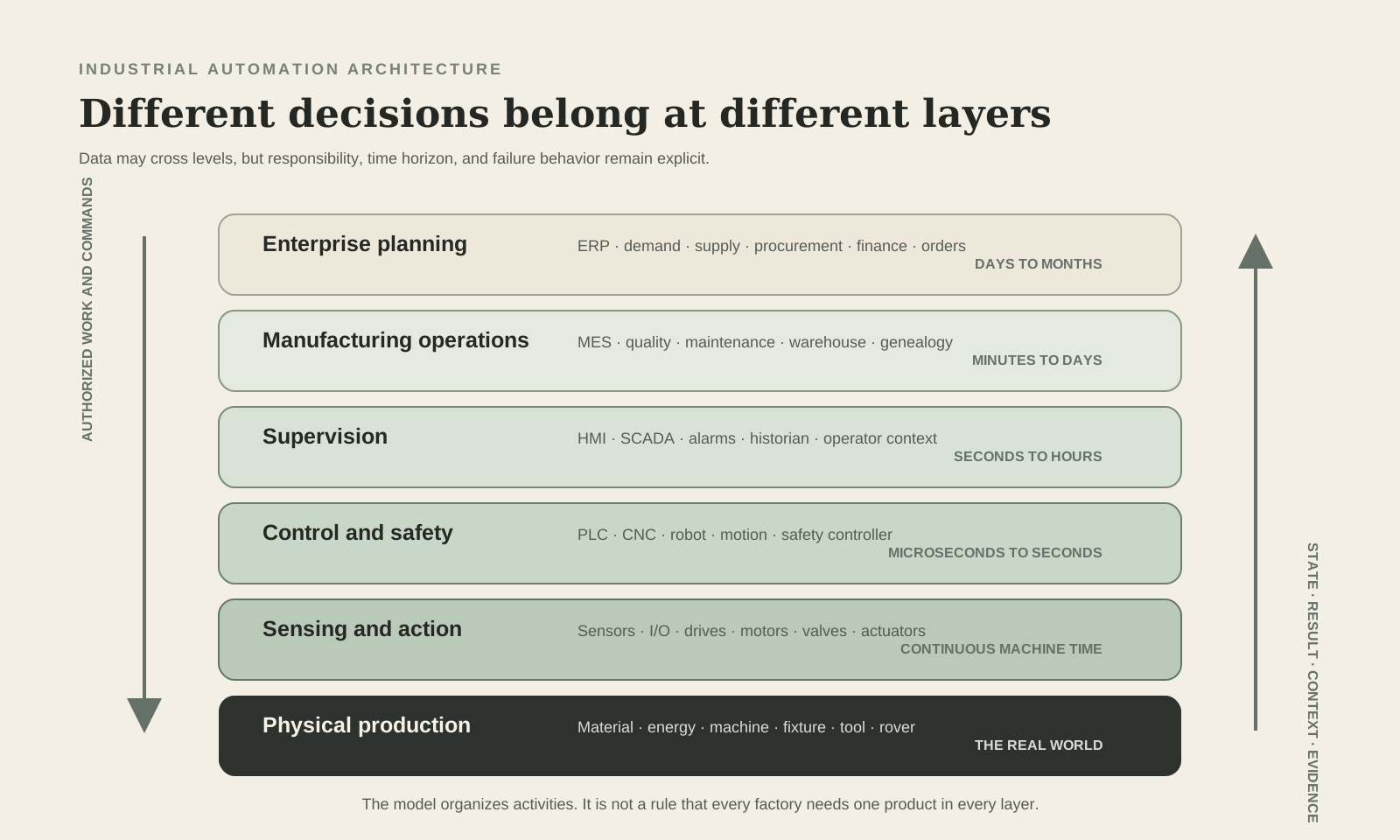
The most important design question is not whether a factory is automated. It is which decision belongs at which layer. Fast motion belongs close to the machine. Safety functions belong in validated safety related control. Cell sequencing belongs in the machine or cell controller. Production dispatch and genealogy belong in manufacturing operations systems. Orders, inventory value, purchasing, and financial commitments belong in enterprise systems. Data may cross these boundaries, but responsibility should remain explicit.
The Factory Nervous System at a Glance
Physical process
Primary Job
Transform, move, hold, inspect, or test
Typical Elements
Machine, fixture, tool, material, rover
Failure Question
What physical state now exists?
Sensing and action
Primary Job
Observe and change the process
Typical Elements
Sensors, I/O, valves, cylinders, motors, drives
Failure Question
Did the real world match the command?
Control and safety
Primary Job
Sequence work and enforce safe behavior
Typical Elements
PLC, motion controller, CNC, robot controller, safety controller
Failure Question
Can the machine respond correctly and reach a safe state?
Supervision
Primary Job
Give operators visibility and permitted control
Typical Elements
HMI, SCADA, alarm and historian services
Failure Question
Can people understand, operate, and recover the process?
Manufacturing operations
Primary Job
Dispatch, track, verify, and improve production
Typical Elements
MES, MOM, quality, maintenance, warehouse, genealogy
Failure Question
Was the right product made with the right resources and evidence?
Enterprise
Primary Job
Plan demand, supply, money, and commitments
Typical Elements
ERP, planning, procurement, finance, order management
Failure Question
What should the business make, buy, deliver, and record?
| Layer | Primary Job | Typical Elements | Failure Question |
|---|---|---|---|
| Physical process | Transform, move, hold, inspect, or test | Machine, fixture, tool, material, rover | What physical state now exists? |
| Sensing and action | Observe and change the process | Sensors, I/O, valves, cylinders, motors, drives | Did the real world match the command? |
| Control and safety | Sequence work and enforce safe behavior | PLC, motion controller, CNC, robot controller, safety controller | Can the machine respond correctly and reach a safe state? |
| Supervision | Give operators visibility and permitted control | HMI, SCADA, alarm and historian services | Can people understand, operate, and recover the process? |
| Manufacturing operations | Dispatch, track, verify, and improve production | MES, MOM, quality, maintenance, warehouse, genealogy | Was the right product made with the right resources and evidence? |
| Enterprise | Plan demand, supply, money, and commitments | ERP, planning, procurement, finance, order management | What should the business make, buy, deliver, and record? |
Black Scarab Weekly
Get the next Black Scarab deep dive
Keep reading now, then get every new deep dive and news report in Thursday's briefing.
Start With the Control Loop
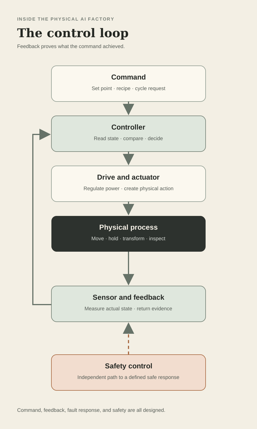
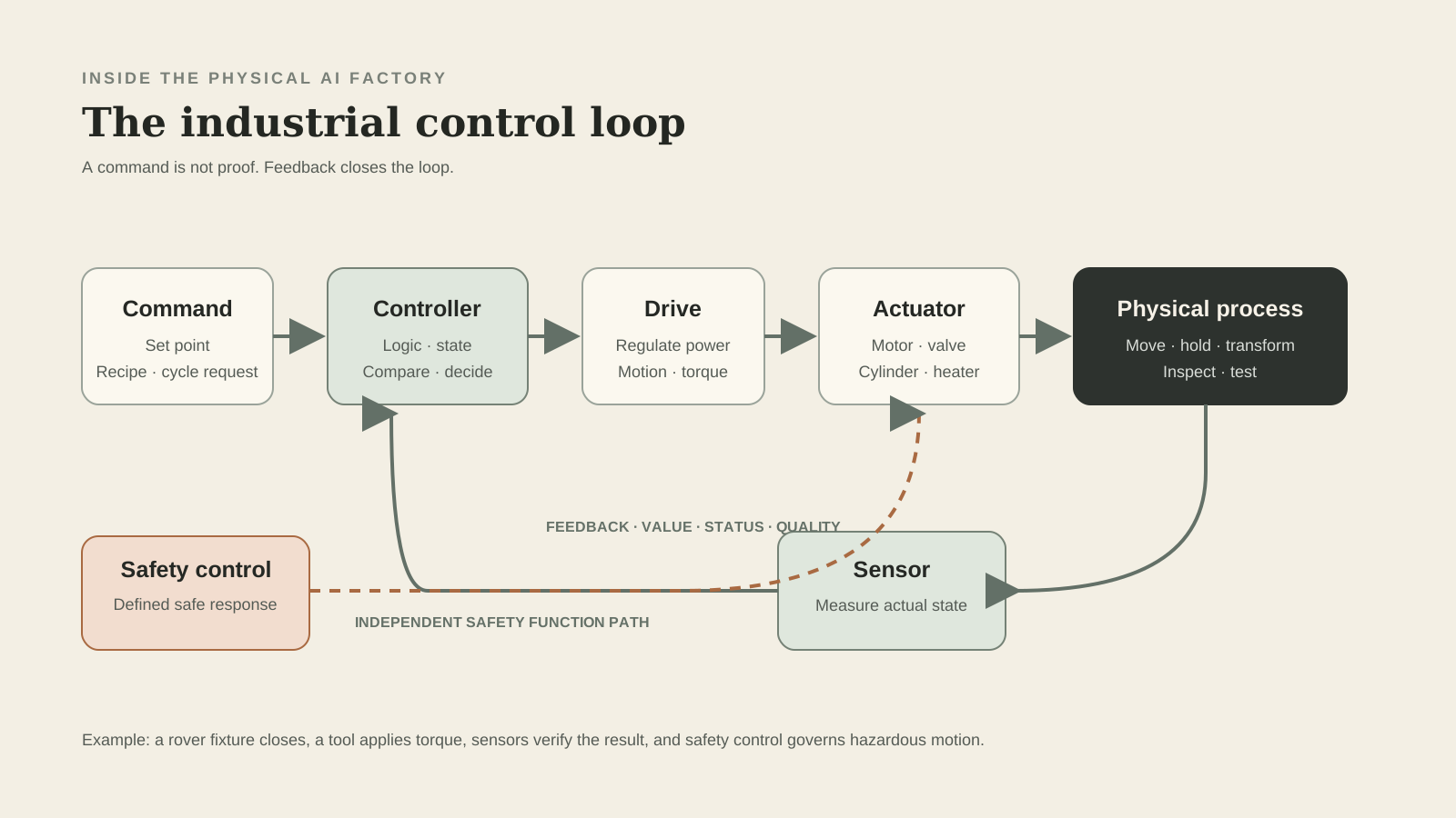
NIST defines a control loop as sensors, controller hardware, actuators, and communication of variables. The controlled condition is measured, compared with a set point or logic state, acted upon, and measured again. Disturbances make feedback necessary because a command is not proof of a result.
Consider a rover wheel torque station. The fixture reports that the rover is present. A clamp sensor confirms the part is secured. The controller permits the tightening sequence. A servo or tightening controller applies a commanded profile. Torque and angle feedback show whether the joint reached its acceptance window. The controller records pass, fail, or fault. If the guard opens or a safety device changes state, the safety function removes or controls hazardous energy according to the validated design.
Open loop control issues a command without using process feedback to correct the result. Closed loop control measures the result and adjusts the command. Both exist in factories. A timed indicator light may be open loop. Servo position, temperature regulation, pressure control, and web tension are usually closed loop. The correct choice depends on the process, required accuracy, dynamics, risk, and evidence.
What a Control Design Must Define
What is controlled?
Example for the Rover Cell
Clamp position, tightening torque, fixture motion, or test voltage
Why It Matters
A vague objective cannot produce a testable control requirement
What is measured?
Example for the Rover Cell
Presence, position, torque, angle, current, temperature, or pressure
Why It Matters
The controller only knows what the sensing path can represent
What changes the process?
Example for the Rover Cell
Servo motor, pneumatic cylinder, contactor, valve, or heater
Why It Matters
The final element determines force, speed, response, and failure modes
What is the permitted state?
Example for the Rover Cell
Correct model, guard closed, fixture homed, tool ready, no active fault
Why It Matters
Sequencing prevents unsafe or defective combinations
What proves completion?
Example for the Rover Cell
Measured result inside a released acceptance window
Why It Matters
A command sent is not the same as work completed
What happens on failure?
Example for the Rover Cell
Stop, controlled stop, deenergize, hold, alarm, reject, or request recovery
Why It Matters
Fault behavior is part of the design, not an afterthought
| Question | Example for the Rover Cell | Why It Matters |
|---|---|---|
| What is controlled? | Clamp position, tightening torque, fixture motion, or test voltage | A vague objective cannot produce a testable control requirement |
| What is measured? | Presence, position, torque, angle, current, temperature, or pressure | The controller only knows what the sensing path can represent |
| What changes the process? | Servo motor, pneumatic cylinder, contactor, valve, or heater | The final element determines force, speed, response, and failure modes |
| What is the permitted state? | Correct model, guard closed, fixture homed, tool ready, no active fault | Sequencing prevents unsafe or defective combinations |
| What proves completion? | Measured result inside a released acceptance window | A command sent is not the same as work completed |
| What happens on failure? | Stop, controlled stop, deenergize, hold, alarm, reject, or request recovery | Fault behavior is part of the design, not an afterthought |
Sensors Turn Physical Conditions Into Signals
A sensor is a claim about the physical world. It may report that a part is present, an axis is at a position, a tank has reached a level, a motor is hot, a tool produced the required torque, or an image contains a suspected defect. The usefulness of the claim depends on range, resolution, accuracy, repeatability, response time, mounting, environment, calibration, diagnostics, and the way the signal reaches the controller.
Discrete sensors usually represent states such as on or off. Analog sensors represent a continuous quantity such as pressure or temperature. Encoders measure position or speed. Vision systems convert light into images and derived measurements. Identification devices connect a physical item with an identity. Condition monitoring sensors observe vibration, current, temperature, sound, lubrication, or other health indicators.
Selection starts with the failure the process must detect. A shiny black rover enclosure, changing ambient light, dust, vibration, electromagnetic noise, cable damage, and target variation can all break an apparently simple presence check. Good automation engineering tests the sensing principle against real parts and abnormal conditions. It also makes failures visible. A sensor stuck on should not quietly look like a continuously present part.
Common Industrial Sensor Families
Inductive proximity
Typical Use
Detect nearby metal without contact
Design Check
Material, range, target size, mounting, and metal background
Rover Example
Confirm a steel fixture pin is seated
Photoelectric
Typical Use
Detect objects with emitted and received light
Design Check
Color, reflectivity, background, alignment, contamination, and ambient light
Rover Example
Detect an enclosure entering the cell
Ultrasonic
Typical Use
Measure presence or distance with sound
Design Check
Target angle, dead zone, air movement, temperature, and cross talk
Rover Example
Check component height in a tote
Pressure and vacuum
Typical Use
Measure pneumatic, hydraulic, or process pressure
Design Check
Range, media compatibility, response, proof pressure, and units
Rover Example
Confirm fixture clamping pressure
Temperature
Typical Use
Measure process or equipment temperature
Design Check
Sensor type, contact, range, lag, wiring, and calibration
Rover Example
Monitor battery test environment
Encoder
Typical Use
Measure rotary or linear position and speed
Design Check
Resolution, absolute or incremental behavior, reference, coupling, and safety need
Rover Example
Track fixture or conveyor position
Force, torque, and load
Typical Use
Measure mechanical effort
Design Check
Range, overload, stiffness, sampling, drift, and calibration
Rover Example
Verify fastener torque or press fit force
Machine vision
Typical Use
Inspect appearance, geometry, code, or assembly
Design Check
Lighting, optics, pose, variation, training data, thresholds, and false decisions
Rover Example
Verify connector presence and orientation
| Sensor | Typical Use | Design Check | Rover Example |
|---|---|---|---|
| Inductive proximity | Detect nearby metal without contact | Material, range, target size, mounting, and metal background | Confirm a steel fixture pin is seated |
| Photoelectric | Detect objects with emitted and received light | Color, reflectivity, background, alignment, contamination, and ambient light | Detect an enclosure entering the cell |
| Ultrasonic | Measure presence or distance with sound | Target angle, dead zone, air movement, temperature, and cross talk | Check component height in a tote |
| Pressure and vacuum | Measure pneumatic, hydraulic, or process pressure | Range, media compatibility, response, proof pressure, and units | Confirm fixture clamping pressure |
| Temperature | Measure process or equipment temperature | Sensor type, contact, range, lag, wiring, and calibration | Monitor battery test environment |
| Encoder | Measure rotary or linear position and speed | Resolution, absolute or incremental behavior, reference, coupling, and safety need | Track fixture or conveyor position |
| Force, torque, and load | Measure mechanical effort | Range, overload, stiffness, sampling, drift, and calibration | Verify fastener torque or press fit force |
| Machine vision | Inspect appearance, geometry, code, or assembly | Lighting, optics, pose, variation, training data, thresholds, and false decisions | Verify connector presence and orientation |
Actuators and Motors Turn Commands Into Work
An actuator converts energy into a physical change. Pneumatic cylinders create linear motion from compressed air. Hydraulic cylinders produce high force from pressurized fluid. Solenoid valves route flow. Electric motors rotate conveyors, pumps, fans, spindles, joints, and positioning axes. Contactors and solid state devices switch electrical loads. The controller requests action, but the actuator and mechanical transmission determine what force, torque, speed, travel, and stopping behavior are physically possible.
A motor is not selected by power alone. The load profile, speed range, starting torque, duty cycle, inertia, acceleration, ambient conditions, enclosure, efficiency, feedback, braking, and mechanical transmission all matter. The drive and motor should be treated as part of a system. The US Department of Energy recommends a system view of motor performance and variable speed control where demand varies.
Pneumatics can be simple and fast, but compressed air is not free and air compressibility affects precision. Hydraulics support high force but introduce fluid, heat, maintenance, and leak considerations. Electric motion offers clean and precise control, but it needs correct sizing, protection, feedback, tuning, and safe energy control. The cheapest component is not necessarily the lowest cost mechanism once utilities, controls, maintenance, downtime, and quality are included.
VFD, Servo, and Simple Motor Starting
Across the line or contactor control
Best Fit
Fixed speed loads with simple start and stop behavior
What It Controls
Power state and direction where designed
Typical Tradeoff
Simple, but limited speed control and higher starting stress may matter
Variable frequency drive
Best Fit
Pumps, fans, conveyors, and other variable speed AC motor loads
What It Controls
Motor frequency, voltage, acceleration, torque behavior, and diagnostics
Typical Tradeoff
Efficient matching of speed to demand, but selection and settings must fit the motor and process
Servo drive
Best Fit
Positioning, synchronized motion, robotics, packaging, and precision assembly
What It Controls
Closed loop position, velocity, torque, and coordinated motion
Typical Tradeoff
High dynamic performance and precision, with more engineering, feedback, tuning, and cost
Stepper drive
Best Fit
Moderate precision positioning where missed motion can be managed
What It Controls
Commanded incremental position, sometimes with feedback
Typical Tradeoff
Accessible and simple for suitable loads, but torque and position assurance need scrutiny
| Method | Best Fit | What It Controls | Typical Tradeoff |
|---|---|---|---|
| Across the line or contactor control | Fixed speed loads with simple start and stop behavior | Power state and direction where designed | Simple, but limited speed control and higher starting stress may matter |
| Variable frequency drive | Pumps, fans, conveyors, and other variable speed AC motor loads | Motor frequency, voltage, acceleration, torque behavior, and diagnostics | Efficient matching of speed to demand, but selection and settings must fit the motor and process |
| Servo drive | Positioning, synchronized motion, robotics, packaging, and precision assembly | Closed loop position, velocity, torque, and coordinated motion | High dynamic performance and precision, with more engineering, feedback, tuning, and cost |
| Stepper drive | Moderate precision positioning where missed motion can be managed | Commanded incremental position, sometimes with feedback | Accessible and simple for suitable loads, but torque and position assurance need scrutiny |
The PLC Runs the Machine Sequence
A programmable logic controller is an industrial computer built to execute control logic reliably around machines and processes. It reads inputs, executes a program, updates outputs, communicates with devices, and performs diagnostics. This simplified scan model is useful, although modern controllers also use periodic tasks, event tasks, motion tasks, communication services, and distributed I/O that do not all wait for one monolithic scan.
The current IEC 61131 Part 3 specifies structured text, ladder diagram, and function block diagram, with sequential function chart elements for organizing programs and function blocks. The language is only one part of a maintainable system. Naming, state models, reusable modules, alarm design, version control, simulation, test records, access control, backups, and change management determine whether the plant can support the code for years.
The rover cell PLC might own fixture sequencing, interlocks, mode management, recipe transfer, handshake with a tightening controller, pass or fail routing, alarms, and production system communication. It should not silently infer a safe state from ordinary process data when a validated safety function is required. It should also reject impossible or stale commands, identify which product variant it is running, and preserve enough context for recovery after a stop.
A Practical PLC Program Structure
I/O mapping
Responsibility
Translate physical and network signals into named program data
Evidence to Test
Correct channel, scale, units, normal state, diagnostic state, and simulation behavior
Mode and state control
Responsibility
Manage off, manual, automatic, homing, fault, recovery, and maintenance states
Evidence to Test
Permitted transitions and behavior after power loss, interruption, or reset
Equipment modules
Responsibility
Control devices such as clamp, conveyor, axis, tool, or test fixture
Evidence to Test
Commands, permissives, interlocks, timeouts, faults, and feedback
Sequence
Responsibility
Coordinate equipment into a repeatable production cycle
Evidence to Test
Normal path, empty path, reject path, restart, recovery, and product change
Recipe and parameters
Responsibility
Apply released settings for the correct product revision
Evidence to Test
Range checks, source, authorization, version, and traceability
Alarms and events
Responsibility
Explain abnormal conditions and guide permitted response
Evidence to Test
Cause, consequence, priority, timestamp, clear condition, and operator action
Interfaces
Responsibility
Exchange commands, status, identity, and results with other systems
Evidence to Test
State handshake, timeout, data quality, duplicate handling, and ownership
| Module | Responsibility | Evidence to Test |
|---|---|---|
| I/O mapping | Translate physical and network signals into named program data | Correct channel, scale, units, normal state, diagnostic state, and simulation behavior |
| Mode and state control | Manage off, manual, automatic, homing, fault, recovery, and maintenance states | Permitted transitions and behavior after power loss, interruption, or reset |
| Equipment modules | Control devices such as clamp, conveyor, axis, tool, or test fixture | Commands, permissives, interlocks, timeouts, faults, and feedback |
| Sequence | Coordinate equipment into a repeatable production cycle | Normal path, empty path, reject path, restart, recovery, and product change |
| Recipe and parameters | Apply released settings for the correct product revision | Range checks, source, authorization, version, and traceability |
| Alarms and events | Explain abnormal conditions and guide permitted response | Cause, consequence, priority, timestamp, clear condition, and operator action |
| Interfaces | Exchange commands, status, identity, and results with other systems | State handshake, timeout, data quality, duplicate handling, and ownership |
Safety Control Is a Separate Engineering Responsibility
A standard control system is designed to make the process operate. A safety related control system performs safety functions that reduce risk. The two may share hardware families, networks, engineering tools, or enclosures, but the safety function has its own risk assessment, required performance, architecture, diagnostics, verification, validation, and change control.
ISO 13849 Part 1 provides a methodology for designing and integrating safety related parts of control systems. IEC 62061 addresses the design, integration, and validation of safety related control systems for machinery. OSHA also requires guarding methods that protect operators from points of operation, rotating parts, flying chips, and other machine hazards. The applicable legal and standards framework depends on the machine and jurisdiction, so qualified safety engineering is essential.
A safety PLC does not make an unsafe machine safe by itself. The complete function starts with the protective device or input, includes logic and diagnostics, ends at the power control elements, and depends on the mechanical system reaching the required safe condition. Emergency stop, guard interlocking, safe torque off, safe speed, light curtains, scanners, pressure release, braking, and restart prevention are different functions. Each needs a defined response and proof that the response works.
Standard Control and Safety Related Control
Primary purpose
Standard Control
Operate the process and meet production requirements
Safety Related Control
Reduce risk by performing defined safety functions
Typical input
Standard Control
Part present, cycle request, process value, recipe
Safety Related Control
Emergency stop, guard switch, protective field, safe position or speed
Typical output
Standard Control
Run conveyor, move axis, open valve, call robot program
Safety Related Control
Remove torque, prevent start, command controlled stop, isolate hazardous action
Design basis
Standard Control
Functional requirement, quality, rate, uptime, maintainability
Safety Related Control
Risk assessment, required performance, architecture, diagnostics, validation
Change discipline
Standard Control
Engineering review and regression test
Safety Related Control
Controlled safety lifecycle with documented verification and validation
AI role
Standard Control
May support optimization or diagnosis within controlled authority
Safety Related Control
Must not casually replace the validated safety function or its deterministic response
| Question | Standard Control | Safety Related Control |
|---|---|---|
| Primary purpose | Operate the process and meet production requirements | Reduce risk by performing defined safety functions |
| Typical input | Part present, cycle request, process value, recipe | Emergency stop, guard switch, protective field, safe position or speed |
| Typical output | Run conveyor, move axis, open valve, call robot program | Remove torque, prevent start, command controlled stop, isolate hazardous action |
| Design basis | Functional requirement, quality, rate, uptime, maintainability | Risk assessment, required performance, architecture, diagnostics, validation |
| Change discipline | Engineering review and regression test | Controlled safety lifecycle with documented verification and validation |
| AI role | May support optimization or diagnosis within controlled authority | Must not casually replace the validated safety function or its deterministic response |
HMI and SCADA Make the Process Legible
A human machine interface gives an operator a structured view of the machine or cell. It can show mode, state, commands, permissives, measurements, alarms, recipes, and maintenance information. A supervisory control and data acquisition system usually spans a wider process or site, collecting data, presenting status, managing alarms, and sometimes providing supervisory commands and history.
The screen should explain the process, not decorate it. Color needs a defined meaning. Alarm priority should reflect consequence and urgency. A stopped sequence should show which permissive is missing. Units, limits, quality, time, source, and communication status should be visible where they affect interpretation. Operator commands need role based permissions and clear feedback that the command was accepted or rejected.
An HMI is not the primary safety device unless the complete safety function is specifically designed and validated for that purpose. A screen can explain that a guard is open, but ordinary HMI communication should not be the only path that stops hazardous motion. The operator view, control logic, and safety logic should agree about machine state without confusing their responsibilities.
CNC and Robot Controllers Are Specialized Control Systems
Computer numerical control coordinates machine axes, spindle behavior, tooling, offsets, and part programs to create a required geometry. The CNC interprets the machining program and manages motion, while a PLC function often handles machine sequencing, doors, clamps, coolant, tool change, auxiliaries, and interlocks. The boundary varies by machine architecture, but the CNC does more than turn a conventional PLC into a machine tool.
A robot system similarly combines several layers. The robot controller coordinates joint motion and kinematics. The application program defines paths, frames, tools, process steps, and handshakes. End effectors, vision, process equipment, guarding, safety functions, and the surrounding PLC make the robot useful as a cell. The robot arm alone is not the automation solution.
For the rover factory, a CNC might machine a low volume fixture plate or prototype bracket. A robot might load a test fixture, apply adhesive, present the rover to inspection, or move completed units. Both need product identification, tool and program control, safe interaction, recovery logic, quality evidence, maintenance access, and an owner who can support the complete cell.
PLC, CNC, Motion Controller, and Robot Controller
PLC
Core Strength
Discrete logic, sequencing, interlocks, process control, and machine coordination
Typical Programming Object
Tags, logic routines, function blocks, states, and equipment modules
Common Integration Need
I/O, drives, instruments, HMI, safety, and production systems
CNC
Core Strength
Tool path execution, spindle control, axis interpolation, and machining functions
Typical Programming Object
Part program, tool data, work offsets, cycles, and machine parameters
Common Integration Need
Machine PLC, probing, tooling, quality, program release, and material handling
Motion controller
Core Strength
High performance coordinated position, velocity, and torque control
Typical Programming Object
Axes, trajectories, cams, gearing, and motion functions
Common Integration Need
Drives, encoders, machine sequence, safety, and process synchronization
Robot controller
Core Strength
Joint coordination, kinematics, path planning, and robot application execution
Typical Programming Object
Frames, tools, positions, paths, jobs, and process instructions
Common Integration Need
End effector, cell PLC, vision, safety, quality, and recovery
| Controller | Core Strength | Typical Programming Object | Common Integration Need |
|---|---|---|---|
| PLC | Discrete logic, sequencing, interlocks, process control, and machine coordination | Tags, logic routines, function blocks, states, and equipment modules | I/O, drives, instruments, HMI, safety, and production systems |
| CNC | Tool path execution, spindle control, axis interpolation, and machining functions | Part program, tool data, work offsets, cycles, and machine parameters | Machine PLC, probing, tooling, quality, program release, and material handling |
| Motion controller | High performance coordinated position, velocity, and torque control | Axes, trajectories, cams, gearing, and motion functions | Drives, encoders, machine sequence, safety, and process synchronization |
| Robot controller | Joint coordination, kinematics, path planning, and robot application execution | Frames, tools, positions, paths, jobs, and process instructions | End effector, cell PLC, vision, safety, quality, and recovery |
Industrial Networks Carry Different Kinds of Truth
A factory network is not one uniform pipe. Hardwired I/O can still be the right answer for simple or safety critical signals. Industrial Ethernet and field networks connect remote I/O, drives, instruments, robots, machine controllers, safety devices, and supervisory systems. Higher layers exchange production context, events, histories, files, and business transactions.
Network selection depends on timing, determinism, topology, device support, diagnostics, safety capability, cybersecurity, lifecycle, and the installed skill base. EtherNet/IP, PROFINET, EtherCAT, Modbus TCP, IO Link, CAN based networks, and vendor specific motion networks solve overlapping but different problems. Protocol names alone do not prove interoperability. A project must define the data model, update behavior, connection ownership, device profiles, diagnostics, failure state, version, and conformance evidence.
OPC UA provides platform independent services, security mechanisms, and information modeling for interoperable exchange from embedded devices toward enterprise systems. It can give data semantic context instead of exposing an unexplained list of tags. It does not remove the need to design identities, units, timestamps, quality, access, certificates, ownership, and lifecycle management.
Questions for Every Industrial Interface
Who owns the command?
Reason
Two systems should not quietly compete for control of one physical action
What does each value mean?
Reason
Name, unit, range, state, product context, and quality prevent false interpretation
How fresh must it be?
Reason
Control, supervision, reporting, and planning operate on different time horizons
What happens when communication fails?
Reason
The machine needs a defined hold, stop, local fallback, reject, or recovery behavior
Can the receiver detect duplicates or stale data?
Reason
Retries and reconnection can otherwise repeat work or apply an old command
How is access controlled?
Reason
Identity, authorization, certificates, segmentation, and logging limit unintended action
How is the interface tested after change?
Reason
Versions, simulation, conformance, regression, and acceptance protect the lifecycle
| Question | Reason |
|---|---|
| Who owns the command? | Two systems should not quietly compete for control of one physical action |
| What does each value mean? | Name, unit, range, state, product context, and quality prevent false interpretation |
| How fresh must it be? | Control, supervision, reporting, and planning operate on different time horizons |
| What happens when communication fails? | The machine needs a defined hold, stop, local fallback, reject, or recovery behavior |
| Can the receiver detect duplicates or stale data? | Retries and reconnection can otherwise repeat work or apply an old command |
| How is access controlled? | Identity, authorization, certificates, segmentation, and logging limit unintended action |
| How is the interface tested after change? | Versions, simulation, conformance, regression, and acceptance protect the lifecycle |
The Factory Software Stack Connects Orders With Evidence
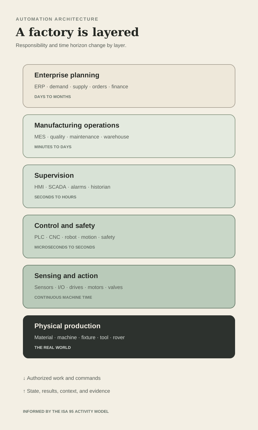
The ISA 95 model describes activities from the physical process and sensing through control, manufacturing operations, and business planning. The model is useful because it organizes responsibility and information exchange. It should not be mistaken for a rule that every plant needs one product in every box or that every message must climb a rigid pyramid.
Enterprise resource planning manages business commitments such as sales orders, purchasing, inventory value, and financial records. Manufacturing operations management and manufacturing execution functions turn production demand into dispatched work, track status, enforce routes, preserve genealogy, and collect results. Quality systems manage specifications, inspections, nonconformance, and corrective action. Warehouse systems manage locations and movements. Maintenance systems manage assets, work, parts, and history. Product lifecycle systems manage product definitions and engineering change.
SCADA, historians, edge services, integration platforms, and data infrastructure move or preserve operating information. Their labels often overlap in the market. Buyers should define required activities, decisions, records, and interfaces before selecting products. A dashboard that visualizes downtime is not automatically an MES. A historian that stores process values is not automatically the authoritative product genealogy record.
Common Factory Software Responsibilities
ERP and planning
Primary Responsibility
Demand, supply, procurement, inventory value, cost, order, and financial commitments
Rover Example
Create the production requirement and confirm material availability
Should Not Become
A direct machine motion controller
MES or MOM
Primary Responsibility
Dispatch, route enforcement, work status, genealogy, resource and result collection
Rover Example
Release the correct rover order and preserve build history
Should Not Become
An ungoverned duplicate of every enterprise and control function
QMS
Primary Responsibility
Specifications, inspection plans, nonconformance, audit, and corrective action
Rover Example
Control acceptance limits and disposition a failed test
Should Not Become
A passive document folder disconnected from production
WMS
Primary Responsibility
Warehouse location, movement, picking, replenishment, and count
Rover Example
Move the released kit to the correct cell
Should Not Become
The owner of machine sequence logic
CMMS or EAM
Primary Responsibility
Asset hierarchy, preventive work, condition, parts, and maintenance history
Rover Example
Schedule fixture calibration and respond to repeated axis faults
Should Not Become
An alarm screen with no work process
PLM
Primary Responsibility
Product definition, configuration, release, and engineering change
Rover Example
Control the rover revision and approved manufacturing definition
Should Not Become
A replacement for shop floor effectivity control
SCADA and historian
Primary Responsibility
Supervision, alarms, time series collection, events, and analysis
Rover Example
Show cell state and retain selected torque or environmental trends
Should Not Become
The only product acceptance record without context and governance
| System Family | Primary Responsibility | Rover Example | Should Not Become |
|---|---|---|---|
| ERP and planning | Demand, supply, procurement, inventory value, cost, order, and financial commitments | Create the production requirement and confirm material availability | A direct machine motion controller |
| MES or MOM | Dispatch, route enforcement, work status, genealogy, resource and result collection | Release the correct rover order and preserve build history | An ungoverned duplicate of every enterprise and control function |
| QMS | Specifications, inspection plans, nonconformance, audit, and corrective action | Control acceptance limits and disposition a failed test | A passive document folder disconnected from production |
| WMS | Warehouse location, movement, picking, replenishment, and count | Move the released kit to the correct cell | The owner of machine sequence logic |
| CMMS or EAM | Asset hierarchy, preventive work, condition, parts, and maintenance history | Schedule fixture calibration and respond to repeated axis faults | An alarm screen with no work process |
| PLM | Product definition, configuration, release, and engineering change | Control the rover revision and approved manufacturing definition | A replacement for shop floor effectivity control |
| SCADA and historian | Supervision, alarms, time series collection, events, and analysis | Show cell state and retain selected torque or environmental trends | The only product acceptance record without context and governance |
Follow One Rover Order From Plan to Production Record
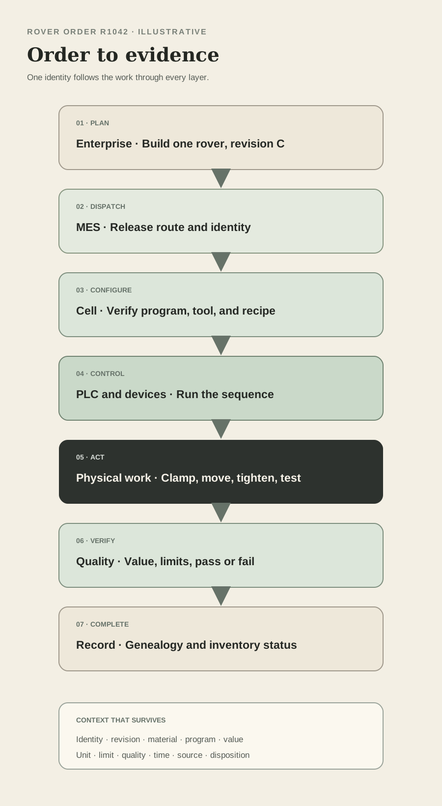
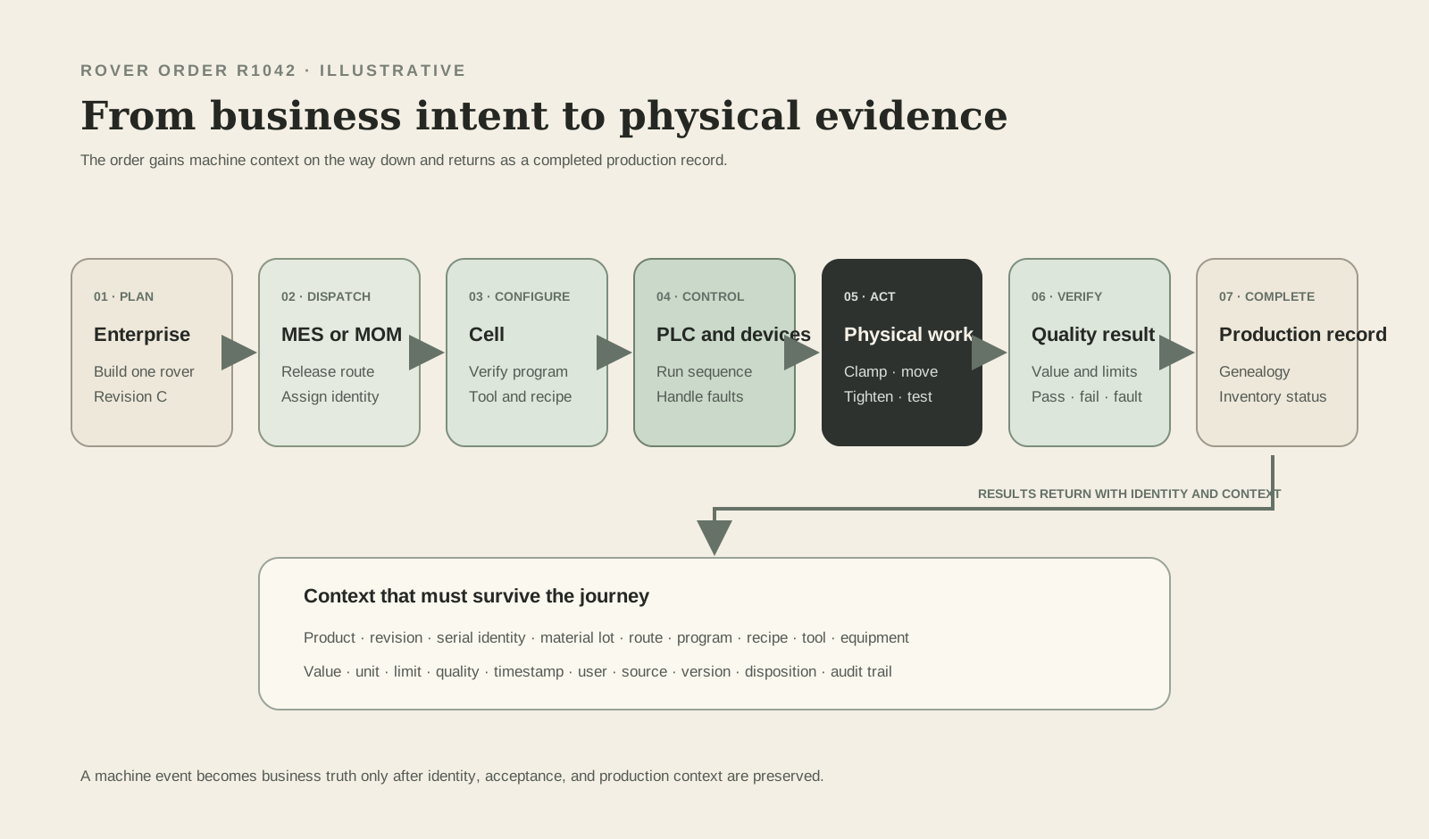
Assume the business needs rover unit R1042 built to released product revision C. The example is illustrative. The exact systems, messages, and approval points differ by factory. The purpose is to show that one order changes form as it moves through planning, dispatch, control, physical work, verification, and completion.
The enterprise system creates or schedules the production requirement. Manufacturing operations verifies the route, material status, revision, resources, and due date, then dispatches work to the rover cell. The warehouse process delivers the kit. The operator identifies the order and unit. The cell checks that its program, recipe, tools, fixture, and connected devices are ready for revision C.
The PLC then owns the immediate sequence. It confirms safe and process permissives, clamps the rover, calls the correct tightening or robot program, and monitors feedback. Specialized controllers regulate the detailed motion or process. Sensors prove physical states. Each operation returns a result with identity, time, units, limits, status, and relevant context. A failure stops or routes the work according to released logic.
Manufacturing operations receives completion and result data, updates genealogy, and advances the unit only when required evidence exists. A quality failure creates a controlled exception rather than a green dashboard. When all required operations pass, the production record closes. Enterprise inventory and order status can then update from a trusted manufacturing event rather than from an operator retyping what the machine already knew.
Rover Order R1042 Through the Stack
1. Plan
Owner
ERP and planning
Instruction or Evidence
Build one rover to satisfy demand
Required Context
Product, quantity, due date, site, and business priority
2. Dispatch
Owner
MES or MOM
Instruction or Evidence
Execute released route for R1042
Required Context
Revision C, serial identity, material, route, resource, and authorization
3. Stage
Owner
Warehouse and operator
Instruction or Evidence
Deliver and verify the kit
Required Context
Part, lot or serial, quantity, location, status, and revision
4. Configure
Owner
Cell control and operator
Instruction or Evidence
Select released recipe and confirm readiness
Required Context
Order, variant, program, tool, fixture, calibration, and permissions
5. Act
Owner
PLC, CNC, robot, motion, and device controllers
Instruction or Evidence
Run the deterministic sequence
Required Context
State, permissives, commands, feedback, timeouts, and fault behavior
6. Verify
Owner
Sensors, process controller, and quality logic
Instruction or Evidence
Return measured result and acceptance decision
Required Context
Value, unit, limits, quality, identity, timestamp, and method
7. Record
Owner
MES, QMS, historian, and genealogy services
Instruction or Evidence
Preserve pass, fail, rework, event, and process evidence
Required Context
Source, version, user, equipment, material, and complete audit context
8. Complete
Owner
Manufacturing operations and ERP
Instruction or Evidence
Close production and update business state
Required Context
Accepted quantity, consumption, disposition, inventory, and order status
| Step | Owner | Instruction or Evidence | Required Context |
|---|---|---|---|
| 1. Plan | ERP and planning | Build one rover to satisfy demand | Product, quantity, due date, site, and business priority |
| 2. Dispatch | MES or MOM | Execute released route for R1042 | Revision C, serial identity, material, route, resource, and authorization |
| 3. Stage | Warehouse and operator | Deliver and verify the kit | Part, lot or serial, quantity, location, status, and revision |
| 4. Configure | Cell control and operator | Select released recipe and confirm readiness | Order, variant, program, tool, fixture, calibration, and permissions |
| 5. Act | PLC, CNC, robot, motion, and device controllers | Run the deterministic sequence | State, permissives, commands, feedback, timeouts, and fault behavior |
| 6. Verify | Sensors, process controller, and quality logic | Return measured result and acceptance decision | Value, unit, limits, quality, identity, timestamp, and method |
| 7. Record | MES, QMS, historian, and genealogy services | Preserve pass, fail, rework, event, and process evidence | Source, version, user, equipment, material, and complete audit context |
| 8. Complete | Manufacturing operations and ERP | Close production and update business state | Accepted quantity, consumption, disposition, inventory, and order status |
Deterministic Control and Physical AI Need a Deliberate Boundary
Conventional automation is strongest when the task, inputs, states, and required response can be defined. It repeats a released sequence, executes motion, enforces interlocks, regulates variables, and records known outcomes. Physical AI becomes interesting when the environment contains meaningful variation that fixed rules cannot economically enumerate, such as variable object pose, visual ambiguity, unstructured movement, complex planning, or patterns across large operating histories.
The boundary should be based on authority and consequence. An AI model may propose a robot grasp, classify an image, forecast a bearing problem, recommend a schedule, or identify an unusual process pattern. The deterministic system can validate range, identity, readiness, collision constraints, process state, and permitted action before execution. A validated safety system remains responsible for the defined safety function.
Learning does not eliminate engineering. The AI function needs an operating design domain, representative evaluation data, confidence handling, latency limits, monitoring, version control, rollback, cybersecurity, and a safe fallback. Human review may be appropriate for rare or costly decisions. A model that performs well on average can still be unsuitable when the missed case creates injury, equipment damage, or an undetected product defect.
Where Determinism Ends and Adaptation Begins
Machine safety
Deterministic Core
Validated safety input, logic, output, diagnostics, and safe state
Possible AI Contribution
Support risk discovery or analyze events outside the live safety function
Required Boundary
AI does not casually replace the validated safety function
Servo motion
Deterministic Core
Real time current, velocity, position, limits, and stop behavior
Possible AI Contribution
Propose a path, tune within approved bounds, or predict wear
Required Boundary
Controller verifies constraints and retains final motion authority
Robot handling
Deterministic Core
Modes, cell states, interlocks, handshake, and permitted execution
Possible AI Contribution
Estimate pose, select grasp, or plan around allowed variation
Required Boundary
Confidence, workspace, collision, tool, payload, and recovery checks
Visual inspection
Deterministic Core
Trigger, identity, image acquisition, result handshake, and reject action
Possible AI Contribution
Detect or segment defects that resist fixed rules
Required Boundary
Validated data, thresholds, drift monitoring, traceable version, and review path
Maintenance
Deterministic Core
Protection trips, alarms, inspection rules, and work authorization
Possible AI Contribution
Estimate remaining life or detect anomalous patterns
Required Boundary
Recommendation does not bypass protection or maintenance approval
Production scheduling
Deterministic Core
Released order, material constraints, labor rules, and capacity commitments
Possible AI Contribution
Generate or improve candidate schedules
Required Boundary
Feasibility checks, explainable changes, planner approval, and rollback
Operator support
Deterministic Core
Permitted commands, procedures, access, and change control
Possible AI Contribution
Search documentation, summarize faults, or propose recovery steps
Required Boundary
Source grounding, role limits, confirmation, and no hidden control path
| Factory Function | Deterministic Core | Possible AI Contribution | Required Boundary |
|---|---|---|---|
| Machine safety | Validated safety input, logic, output, diagnostics, and safe state | Support risk discovery or analyze events outside the live safety function | AI does not casually replace the validated safety function |
| Servo motion | Real time current, velocity, position, limits, and stop behavior | Propose a path, tune within approved bounds, or predict wear | Controller verifies constraints and retains final motion authority |
| Robot handling | Modes, cell states, interlocks, handshake, and permitted execution | Estimate pose, select grasp, or plan around allowed variation | Confidence, workspace, collision, tool, payload, and recovery checks |
| Visual inspection | Trigger, identity, image acquisition, result handshake, and reject action | Detect or segment defects that resist fixed rules | Validated data, thresholds, drift monitoring, traceable version, and review path |
| Maintenance | Protection trips, alarms, inspection rules, and work authorization | Estimate remaining life or detect anomalous patterns | Recommendation does not bypass protection or maintenance approval |
| Production scheduling | Released order, material constraints, labor rules, and capacity commitments | Generate or improve candidate schedules | Feasibility checks, explainable changes, planner approval, and rollback |
| Operator support | Permitted commands, procedures, access, and change control | Search documentation, summarize faults, or propose recovery steps | Source grounding, role limits, confirmation, and no hidden control path |
Cybersecurity Is Part of Machine Reliability
NIST SP 800 Part 82 Revision 3 emphasizes that operational technology security must account for performance, reliability, and safety requirements. An automation network cannot be secured by treating it as an ordinary office network, nor should operational urgency become an excuse for unmanaged remote access, shared accounts, unsupported systems, or flat connectivity.
Start with an asset inventory, architecture, data flows, trust boundaries, owners, supported versions, backups, and recovery procedures. Segment by risk and function. Control remote access. Use named identities and least privilege where the technology supports them. Manage removable media and engineering workstations. Monitor changes and unusual communication. Test backups by restoring them. Coordinate patching with vendors, operations, safety, and production windows.
Availability is not merely keeping the network online. The plant must recover the correct controller program, robot job, drive parameters, safety configuration, HMI application, recipe, certificate, and interface version. A backup without a tested device replacement process may still leave the line stopped. A secure design also protects the integrity of product identity and quality records, because false context can produce a physically correct operation on the wrong product.
Commission the System as One Production Machine
Automation acceptance should begin before hardware arrives. Define the sequence, modes, states, interfaces, alarms, recipes, safety functions, data records, user roles, performance targets, and recovery cases. Simulate what can be tested early. A factory acceptance test can verify panels, code, devices, and representative sequences. Site acceptance adds installed utilities, real material, connected systems, operators, maintenance, production conditions, and final safety validation.
Test normal production and abnormal production. Remove a sensor. Interrupt communication. Present the wrong part. Lose power during a sequence. Open a guard at different moments. Reject a measurement. Restore from backup. Change a recipe with and without permission. Restart after the robot has moved but the production record has not updated. Verify that each layer reaches a known condition without duplicate work or lost genealogy.
The delivered system needs more than source code. It needs network drawings, electrical and pneumatic drawings, bills of material, safety documentation, risk assessment, programs, parameters, licenses, certificates, backups, version history, interface definitions, test records, calibration information, spare strategy, maintenance instructions, training, and named ownership. The plant buys a lifecycle, not only a successful demonstration.
Automation Acceptance Evidence
Function
Minimum Evidence
Approved sequence, modes, states, recipes, interlocks, cycle behavior, and acceptance results
Safety
Minimum Evidence
Risk assessment, safety requirement, design calculation, verification, validation, and controlled record
Interfaces
Minimum Evidence
Data definition, ownership, state handshake, timeout, quality, failure response, version, and test
Performance
Minimum Evidence
Representative cycle, variation, faults, recovery, capacity, and quality under agreed conditions
Operations
Minimum Evidence
Operator tasks, alarms, permissions, work instructions, training, and escalation
Maintenance
Minimum Evidence
Diagnostics, access, spares, preventive work, calibration, backups, restore test, and vendor support
Cybersecurity
Minimum Evidence
Inventory, architecture, accounts, remote access, segmentation, hardening, logging, recovery, and update process
Lifecycle
Minimum Evidence
Source files, versions, licenses, certificates, change control, document owner, and obsolescence plan
| Area | Minimum Evidence |
|---|---|
| Function | Approved sequence, modes, states, recipes, interlocks, cycle behavior, and acceptance results |
| Safety | Risk assessment, safety requirement, design calculation, verification, validation, and controlled record |
| Interfaces | Data definition, ownership, state handshake, timeout, quality, failure response, version, and test |
| Performance | Representative cycle, variation, faults, recovery, capacity, and quality under agreed conditions |
| Operations | Operator tasks, alarms, permissions, work instructions, training, and escalation |
| Maintenance | Diagnostics, access, spares, preventive work, calibration, backups, restore test, and vendor support |
| Cybersecurity | Inventory, architecture, accounts, remote access, segmentation, hardening, logging, recovery, and update process |
| Lifecycle | Source files, versions, licenses, certificates, change control, document owner, and obsolescence plan |
Ten Common Automation Mistakes
The first mistake is automating an unstable or poorly understood process. The second is selecting components before defining the control and safety requirements. The third is treating a sensor signal as unquestionable truth. The fourth is assuming that a robot arm, PLC, or software license is a complete production system. The fifth is using one system as the ungoverned owner of every decision.
The sixth is designing only the normal automatic cycle and leaving manual mode, faults, restarts, rejects, and recovery to the end. The seventh is mixing ordinary control and safety responsibility without a validated architecture. The eighth is connecting systems without defining identity, time, units, quality, ownership, stale data, or failure behavior. The ninth is buying a dashboard before defining the operating action it should support.
The tenth is adding AI because variation exists without defining the allowed decision, consequence, evaluation evidence, fallback, monitor, and owner. Physical AI should enlarge the set of conditions the factory can handle while preserving a clear path back to deterministic control and safe operation.
Your Industrial Automation Checkpoint
You should now be able to trace a machine action from sensor through controller, drive, actuator, process, and feedback. You should be able to distinguish a standard PLC from a safety controller, a VFD from a servo drive, a CNC from a general machine sequence, an HMI from an MES, and an enterprise order from a real time control command.
The central idea is that automation is an architecture of decisions. Fast, consequential, and safety related decisions stay close to validated control. Production systems add identity, route, genealogy, and coordination. Enterprise systems add business commitments. Physical AI can perceive, recommend, plan, and adapt where variation justifies it, but only inside an engineered boundary with deterministic checks, monitored performance, and a safe fallback.
Five Questions You Should Now Be Able to Answer
What makes a control loop?
What a Good Answer Contains
Sensor, measured variable, controller, set point or logic, actuator, process, disturbance, and feedback
What does a PLC do?
What a Good Answer Contains
Reads state, executes released logic, sequences equipment, updates outputs, communicates, and diagnoses faults
Why is safety control separate?
What a Good Answer Contains
It performs defined risk reduction with required architecture, diagnostics, verification, validation, and safe state
How does a production order reach a machine?
What a Good Answer Contains
Planning becomes dispatched work, product context, cell configuration, deterministic action, measured result, and genealogy
Where can physical AI add value?
What a Good Answer Contains
Where variation benefits from perception, prediction, planning, or adaptation inside controlled authority and fallback
| Question | What a Good Answer Contains |
|---|---|
| What makes a control loop? | Sensor, measured variable, controller, set point or logic, actuator, process, disturbance, and feedback |
| What does a PLC do? | Reads state, executes released logic, sequences equipment, updates outputs, communicates, and diagnoses faults |
| Why is safety control separate? | It performs defined risk reduction with required architecture, diagnostics, verification, validation, and safe state |
| How does a production order reach a machine? | Planning becomes dispatched work, product context, cell configuration, deterministic action, measured result, and genealogy |
| Where can physical AI add value? | Where variation benefits from perception, prediction, planning, or adaptation inside controlled authority and fallback |
Next in the Series
Part 7 will move from automation that repeats a defined sequence to physical AI that can interpret and adapt. We will connect robotics, machine vision, edge inference, digital twins, predictive maintenance, autonomous material movement, and intelligent production decisions without losing sight of safety, process capability, or economics.
The rover factory will return again. We will identify the applications where learning can outperform fixed rules, define the data and edge architecture each application needs, and examine how a factory can test adaptive behavior before granting it more authority over physical work.
Research Method
This report uses NIST guidance for the control loop and operational technology security. IEC 61131 Part 3 supports the programmable controller language discussion. ISO 13849 Part 1 and IEC 62061 support the safety related control boundary. OSHA materials support the general guarding requirement. ISA 95 supports the enterprise and manufacturing activity model. OPC Foundation materials support the interoperability and information modeling discussion. US Department of Energy Better Plants materials support the motor and drive system view.
Protocol organizations and supplier documentation were reviewed to confirm terminology and representative architectures. Product names and protocol families are examples, not endorsements or claims that one technology fits every application. Capabilities described by vendors are treated as vendor claims unless independently verified in a specific deployment.
The rover order, cell sequence, program structure, interface questions, acceptance framework, and deterministic versus adaptive boundary are Black Scarab teaching frameworks. They do not describe a real factory, validated safety design, legal requirement, guaranteed performance, or recommended purchase. Industrial automation requires qualified control, electrical, mechanical, safety, cybersecurity, manufacturing, quality, operations, and maintenance review for the actual application and jurisdiction.
Continue the series
Inside the Physical AI FactoryPart 6 of 8

About the author
Rodolfo Garcia Calderoni, CFA
Rodolfo is the founder of Black Scarab, where he covers the technologies and commercial signals shaping physical AI adoption.
Meet RodolfoBlack Scarab Weekly
Catch up on physical AI in one email
Every new Black Scarab deep dive and news report, collected into one clear Thursday briefing.
Related Insights
Manufacturing
How to Design a Manufacturing Plant: Process Flow, Factory Layout, Utilities, and Site Selection
A first principles guide to turning a product, production route, and capacity target into a practical factory layout, utility plan, site decision, and expansion path.
Read related insight
Manufacturing
Who Builds a Factory? Siemens, Rockwell, FANUC, Machine Builders, and Integrators Explained
A practical map of the companies behind industrial production, from equipment and controls suppliers to machine builders, integrators, engineering firms, contractors, software providers, and contract manufacturers.
Read related insight
Manufacturing
How a Product Is Manufactured: From Bill of Materials to Production Line
A worked manufacturing plan for an autonomous inspection rover, from product architecture and supplier choices to routing, quality, cost, and capacity for the first 1,000 units.
Read related insight
Next Step
Explore a commercial opportunity in Mexico
If you are exploring how a physical AI technology could fit the Mexican market, Black Scarab can help assess the opportunity, map relevant stakeholders, and define a credible commercial next step.