
Inside the Physical AI Factory · Part 5 of 8
How to Design a Manufacturing Plant: Process Flow, Factory Layout, Utilities, and Site Selection
A first principles guide to turning a product, production route, and capacity target into a practical factory layout, utility plan, site decision, and expansion path.
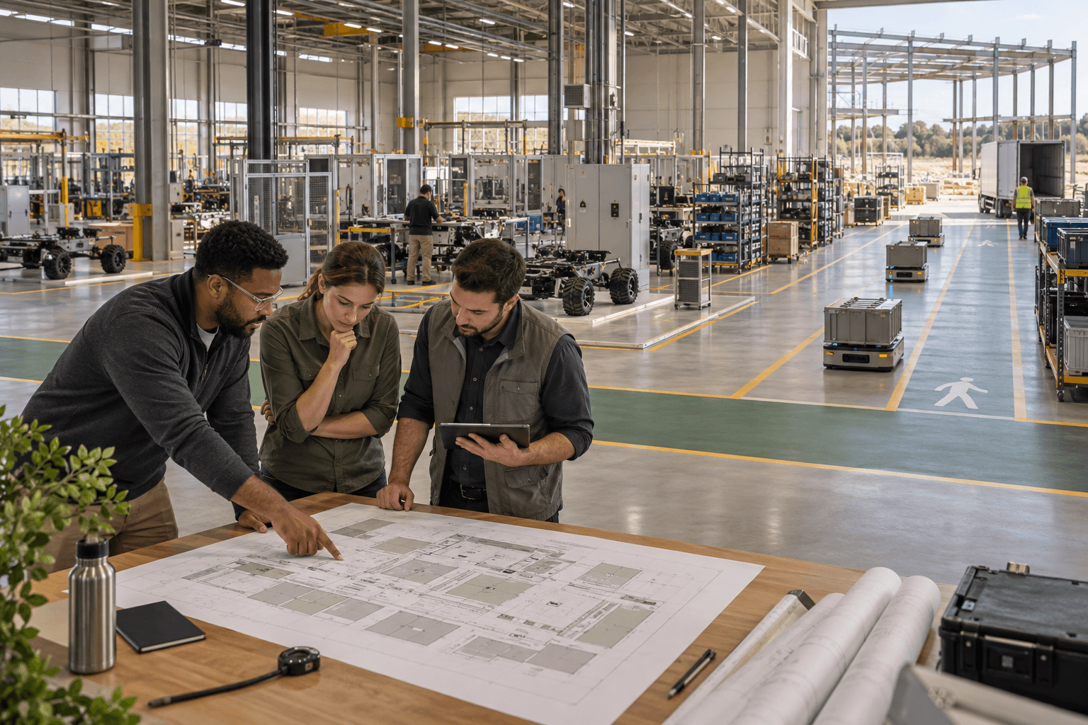
This is Part 5 of Inside the Physical AI Factory. Part 1 mapped the plant. Part 2 opened the machines. Part 3 turned a hypothetical autonomous inspection rover into a bill of materials and production route. Part 4 identified the companies that could supply and integrate the system. Now the route becomes a building.
A factory layout is not an exercise in fitting rectangles onto a floor plan. It is a physical expression of the operating model. Product design determines the work. Demand determines the rate. The route determines which processes must connect. Equipment determines space, access, foundations, and utilities. Inventory policy determines storage. Quality and safety rules determine separation. The site and building constrain every choice.
The sequence matters because a beautiful plan can still be a poor factory. Machines may fit while materials cross each other all day. A large warehouse may hide slow purchasing and unreliable suppliers. A cheap building may require expensive power, ventilation, drainage, fire protection, or floor reinforcement. An automation ready aisle may be too narrow once charging, staging, pedestrians, and fault recovery are considered.
This report follows the hypothetical rover from a production brief to a progressive plant plan for 10 prototypes, 100 commercial units, and capacity for 1,000 units annually. Every area and dimension is illustrative. The purpose is to teach the decisions and evidence behind a layout, not to provide a construction drawing or a universal code solution.
The Short Answer
Design the production system before designing the building around it. Define the accepted product, annual volume, mix, route, process time, uptime assumption, quality gates, inventory policy, make versus buy boundary, workforce, and growth case. Only then can the team estimate equipment, space, utilities, material movement, and facility requirements.
The design should advance from one dimension to three. First, map the sequence of work. Second, test capacity and buffers. Third, arrange departments and flows. Fourth, place real equipment with service access and utility connections. Fifth, validate the design against safety, building, environmental, operational, and expansion requirements. Simulation can test behavior, but it cannot repair weak input assumptions.
The Plant Design Brief at a Glance
Product
Question
What is made, what varies, and what counts as accepted?
Required Evidence
Released drawings, bill of materials, specifications, test limits, and change forecast
Demand
Question
How many units are needed by period and how uncertain is the forecast?
Required Evidence
Base, downside, upside, seasonality, product mix, and launch schedule
Process
Question
Which steps transform, assemble, inspect, calibrate, test, and pack the product?
Required Evidence
Routing, process times, yields, batch rules, rework paths, and traceability needs
Resources
Question
Which people, machines, tools, suppliers, and systems perform the route?
Required Evidence
Capacity model, staffing plan, equipment data, supplier capability, and maintenance plan
Facility
Question
What must the building and site provide?
Required Evidence
Space, floor loads, clear heights, docks, utilities, environment, access, and code review
Economics
Question
Which design produces acceptable service, risk, and return?
Required Evidence
Capital, operating cost, working capital, ramp, contingency, and expansion cases
| Input | Question | Required Evidence |
|---|---|---|
| Product | What is made, what varies, and what counts as accepted? | Released drawings, bill of materials, specifications, test limits, and change forecast |
| Demand | How many units are needed by period and how uncertain is the forecast? | Base, downside, upside, seasonality, product mix, and launch schedule |
| Process | Which steps transform, assemble, inspect, calibrate, test, and pack the product? | Routing, process times, yields, batch rules, rework paths, and traceability needs |
| Resources | Which people, machines, tools, suppliers, and systems perform the route? | Capacity model, staffing plan, equipment data, supplier capability, and maintenance plan |
| Facility | What must the building and site provide? | Space, floor loads, clear heights, docks, utilities, environment, access, and code review |
| Economics | Which design produces acceptable service, risk, and return? | Capital, operating cost, working capital, ramp, contingency, and expansion cases |
Black Scarab Weekly
Get the next Black Scarab deep dive
Keep reading now, then get every new deep dive and news report in Thursday's briefing.
Follow the Design Sequence
Factory design is iterative, but it should not be random. NIST describes factory design as a connected activity model that moves through production planning, line design, layout, material handling, support systems, information systems, and verification. The model is useful because it exposes feedback loops. A utility constraint can change equipment. An equipment choice can change the route. A revised route can change the building.
The practical sequence below begins with the operating result and delays irreversible decisions until the evidence becomes strong enough. Each gate should produce an artifact that the next team can inspect. A demand number without a mix assumption is incomplete. A layout without a route is decoration. A site comparison without utility evidence is a real estate opinion.
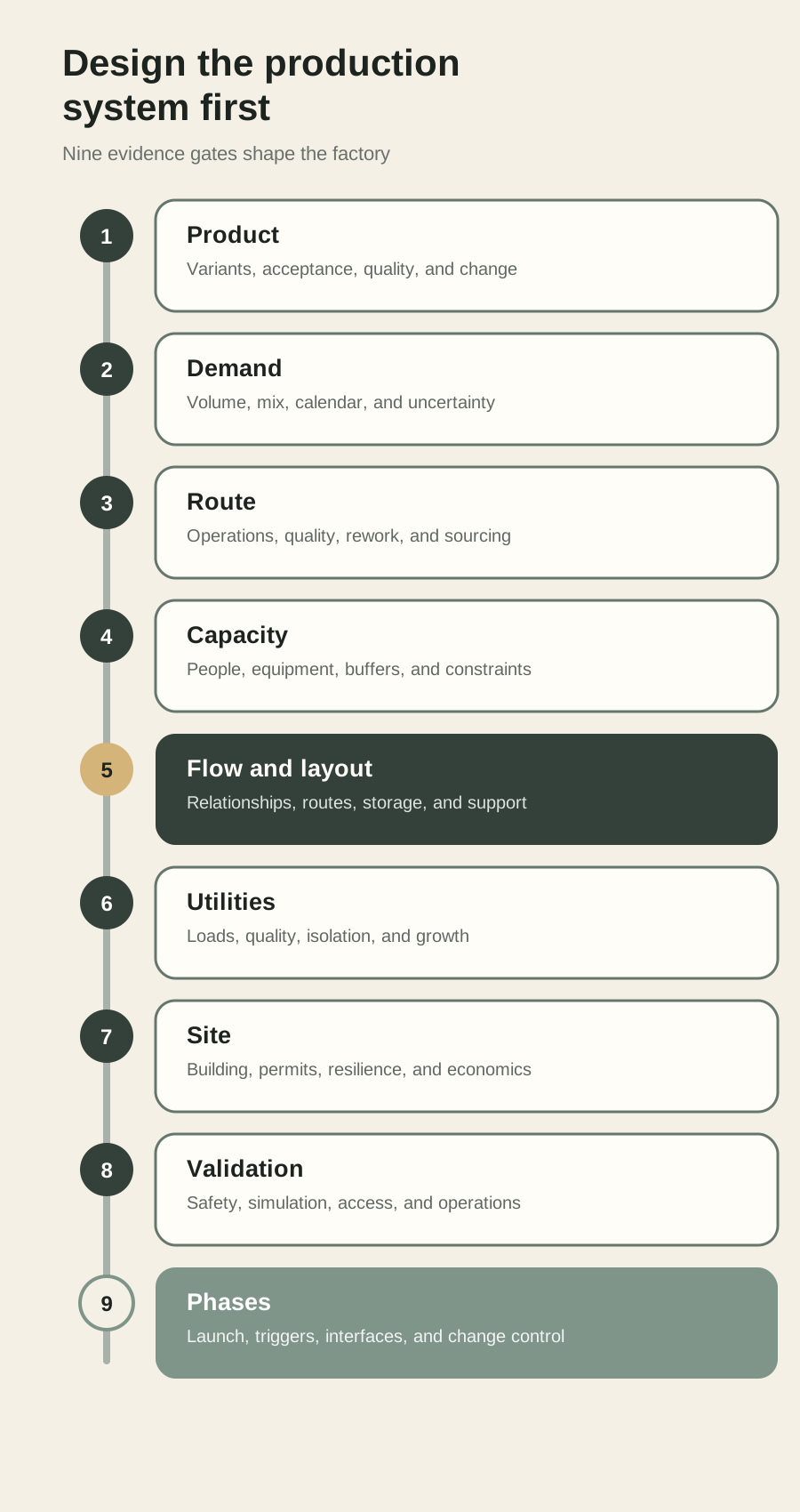
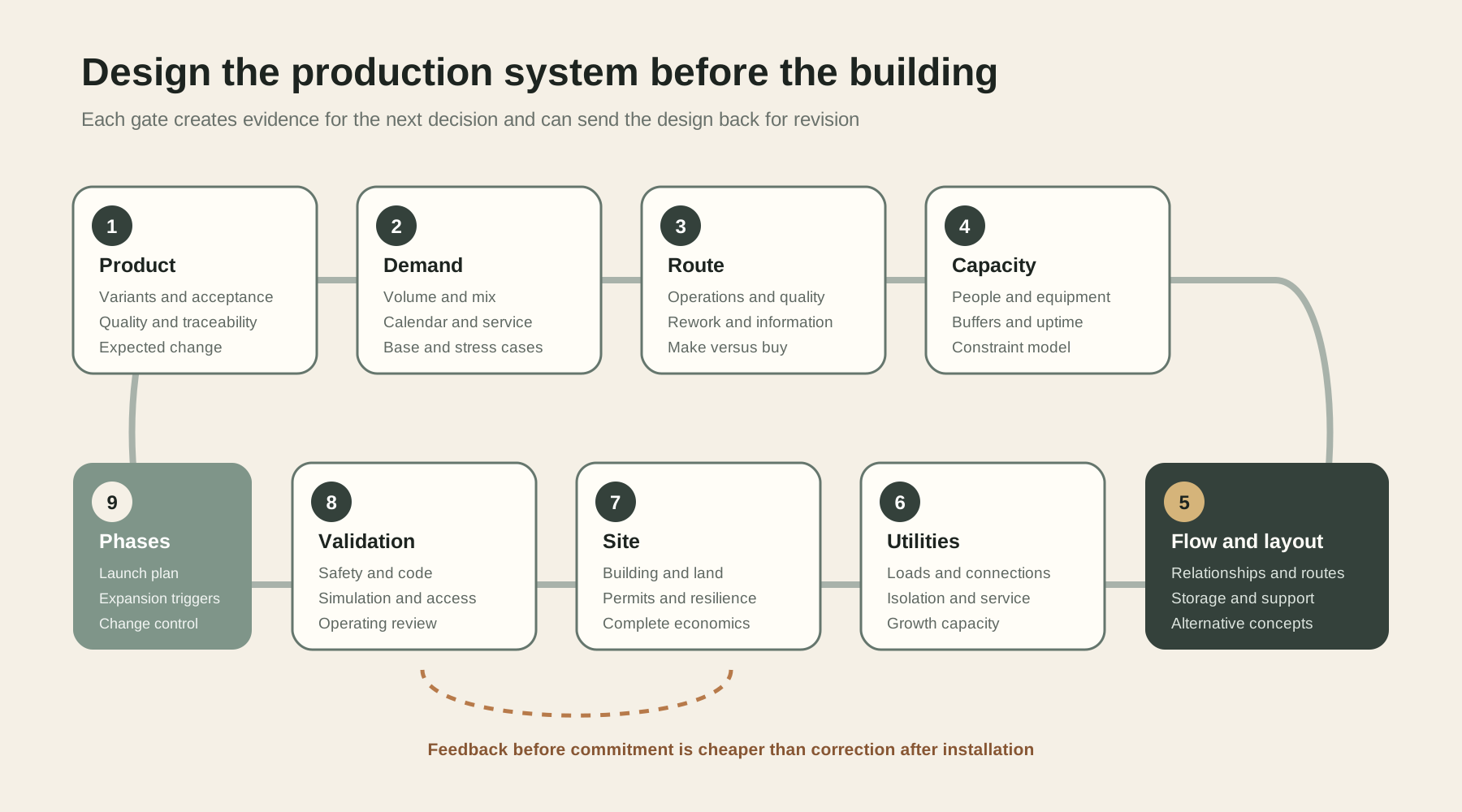
Nine Factory Design Gates
1
Decision
Define the product and accepted output
Output
Product family, variants, quality limits, and traceability boundary
2
Decision
Set volume, mix, and service targets
Output
Demand cases, operating calendar, takt requirement, and uncertainty range
3
Decision
Build the production route
Output
Operation sequence, process data, quality gates, rework, and outsourcing boundary
4
Decision
Model capacity and resources
Output
People, equipment, tooling, buffers, uptime, and constraint model
5
Decision
Create flow and block layouts
Output
Department relationships, material routes, storage, and alternative concepts
6
Decision
Develop equipment and utility layout
Output
Real footprints, access envelopes, power, air, water, exhaust, network, and support space
7
Decision
Screen sites and buildings
Output
Verified site shortlist, gap cost, schedule risk, permitting path, and resilience review
8
Decision
Validate the complete design
Output
Safety, code, simulation, constructability, maintainability, and operating reviews
9
Decision
Freeze phases and expansion triggers
Output
Launch layout, future layout, reserved interfaces, decision dates, and change control
| Gate | Decision | Output |
|---|---|---|
| 1 | Define the product and accepted output | Product family, variants, quality limits, and traceability boundary |
| 2 | Set volume, mix, and service targets | Demand cases, operating calendar, takt requirement, and uncertainty range |
| 3 | Build the production route | Operation sequence, process data, quality gates, rework, and outsourcing boundary |
| 4 | Model capacity and resources | People, equipment, tooling, buffers, uptime, and constraint model |
| 5 | Create flow and block layouts | Department relationships, material routes, storage, and alternative concepts |
| 6 | Develop equipment and utility layout | Real footprints, access envelopes, power, air, water, exhaust, network, and support space |
| 7 | Screen sites and buildings | Verified site shortlist, gap cost, schedule risk, permitting path, and resilience review |
| 8 | Validate the complete design | Safety, code, simulation, constructability, maintainability, and operating reviews |
| 9 | Freeze phases and expansion triggers | Launch layout, future layout, reserved interfaces, decision dates, and change control |
Begin With Flow, Not Square Feet
The first drawing should show the product route without a building. For the rover, purchased frames, motors, gearboxes, batteries, cameras, sensors, circuit boards, and harnesses enter receiving. Incoming inspection samples or verifies critical items. Kitting gathers the correct revision of each component. Mechanical assembly builds the chassis. Electrical assembly installs power and signal paths. Software loading and calibration establish device identity. Functional test proves the complete unit. Final inspection releases it to packaging and finished goods.
That sequence has side paths. A failed battery inspection needs quarantine and supplier disposition. A test failure needs a controlled diagnosis and rework loop. Calibration needs reference equipment and records. Engineering changes need a clear effectivity point so old and new parts do not mix. Waste, returns, tools, maintenance parts, and empty packaging move too. The layout must accommodate the exceptions because production eventually becomes a sequence of exceptions.
NIST describes value stream mapping as a method for visualizing material, process, and information flow. A block layout should begin with that shared operating picture. A spaghetti diagram can then expose distance and crossing paths. The objective is not always the shortest possible route. It is a safe, understandable route with controlled inventory and few unnecessary touches.
The Rover Production Route
Receiving
Primary Input
Supplier shipments and records
Accepted Output
Identified material in the system
Layout Consequence
Dock, weather protection, count area, and discrepancy hold
Incoming quality
Primary Input
Risk selected parts
Accepted Output
Accepted, rejected, or quarantined material
Layout Consequence
Inspection bench, measurement environment, secure hold, and data access
Storage and kitting
Primary Input
Released inventory and work order
Accepted Output
Complete kit at the correct revision
Layout Consequence
Point of use stock, replenishment routes, supermarkets, and kit staging
Mechanical assembly
Primary Input
Frame, motion parts, fasteners, and fixtures
Accepted Output
Mechanically complete rover
Layout Consequence
Ergonomic stations, lifting aids, tooling, torque control, and work in process
Electrical assembly
Primary Input
Harnesses, battery, boards, sensors, and camera
Accepted Output
Electrically complete rover
Layout Consequence
Electrostatic controls where required, protected battery work, and cable test access
Software and calibration
Primary Input
Complete hardware and released software
Accepted Output
Configured and calibrated rover
Layout Consequence
Network, controlled references, fixtures, version records, and quiet test conditions
Functional test
Primary Input
Configured rover
Accepted Output
Evidence that required functions pass
Layout Consequence
Safe test zone, charging, fault containment, data capture, and rework route
Pack and ship
Primary Input
Released rover and accessories
Accepted Output
Protected shipment with complete records
Layout Consequence
Packaging material, final audit, finished goods, and outbound dock access
| Stage | Primary Input | Accepted Output | Layout Consequence |
|---|---|---|---|
| Receiving | Supplier shipments and records | Identified material in the system | Dock, weather protection, count area, and discrepancy hold |
| Incoming quality | Risk selected parts | Accepted, rejected, or quarantined material | Inspection bench, measurement environment, secure hold, and data access |
| Storage and kitting | Released inventory and work order | Complete kit at the correct revision | Point of use stock, replenishment routes, supermarkets, and kit staging |
| Mechanical assembly | Frame, motion parts, fasteners, and fixtures | Mechanically complete rover | Ergonomic stations, lifting aids, tooling, torque control, and work in process |
| Electrical assembly | Harnesses, battery, boards, sensors, and camera | Electrically complete rover | Electrostatic controls where required, protected battery work, and cable test access |
| Software and calibration | Complete hardware and released software | Configured and calibrated rover | Network, controlled references, fixtures, version records, and quiet test conditions |
| Functional test | Configured rover | Evidence that required functions pass | Safe test zone, charging, fault containment, data capture, and rework route |
| Pack and ship | Released rover and accessories | Protected shipment with complete records | Packaging material, final audit, finished goods, and outbound dock access |
Capacity Turns the Route Into Space
Annual demand does not directly tell the designer how many stations are needed. The calculation needs an operating calendar, shift pattern, planned downtime, changeover, yield, mix, and variability. A simple theoretical capacity can be calculated from available production time divided by effective cycle time, but the answer should be tested against real constraints rather than treated as truth.
Suppose the illustrative rover plan requires 1,000 accepted units each year. If the plant operates 230 days on one shift, the average requirement is about 4.35 accepted units per day. That average is not a station design. Supplier deliveries may arrive in lots. Customers may order unevenly. Rework may consume capacity. A calibration fixture may become the constraint even when assembly has spare labor. The team should model at least a base case, a stressed demand case, and a disrupted case.
Space follows resources and movement. A workstation needs the operator envelope, incoming material, outgoing work, tools, information, safe access, service access, and abnormal material area. A machine needs loading space, doors, guarding, panels, chip or waste handling, maintenance access, and removal paths for major components. A rack needs forklift or tugger access, fire protection review, and inventory identification. Adding only machine footprints creates a plan that cannot operate.
Capacity Questions Before Layout
What is the required rate?
Weak Assumption
Annual demand divided by 365 days
Better Evidence
Demand by period, operating calendar, shift plan, service target, and ramp
Which step constrains output?
Weak Assumption
The longest listed cycle time
Better Evidence
Effective cycle, uptime, changeover, staffing, yield, queue, and shared resource analysis
How much buffer is needed?
Weak Assumption
Fill every open area with inventory
Better Evidence
Replenishment frequency, supplier variation, process decoupling, risk, and recovery time
How much space does equipment need?
Weak Assumption
Vendor footprint only
Better Evidence
Operating, guarding, service, loading, utility, rigging, and future change envelopes
How much growth should be installed?
Weak Assumption
Build the upside case immediately
Better Evidence
Phased triggers, reserved interfaces, lead times, and cost of later disruption
| Question | Weak Assumption | Better Evidence |
|---|---|---|
| What is the required rate? | Annual demand divided by 365 days | Demand by period, operating calendar, shift plan, service target, and ramp |
| Which step constrains output? | The longest listed cycle time | Effective cycle, uptime, changeover, staffing, yield, queue, and shared resource analysis |
| How much buffer is needed? | Fill every open area with inventory | Replenishment frequency, supplier variation, process decoupling, risk, and recovery time |
| How much space does equipment need? | Vendor footprint only | Operating, guarding, service, loading, utility, rigging, and future change envelopes |
| How much growth should be installed? | Build the upside case immediately | Phased triggers, reserved interfaces, lead times, and cost of later disruption |
The rover volumes and calculations in this report are illustrative teaching examples, not a production forecast or quoted operating plan.
Choose a Layout That Matches the Work
Four common layout families help organize the decision. A process layout groups similar resources, such as machining in one department and inspection in another. A product layout places operations in the production sequence. A cellular layout brings the resources for a product family together. A fixed position layout keeps a large product in place while people and equipment move to it.
No family is inherently superior. Process layouts support variety and shared expertise but can create long routes and queues. Product layouts can deliver clear flow at stable volume but may be brittle when the product or mix changes. Cells can balance flow and flexibility but may duplicate equipment. Fixed position work fits aircraft, ships, buildings, and other products that are difficult to move, but coordination becomes the central challenge.
The rover plant is likely to combine them. Early prototypes may use a flexible workshop organized by capability. At 100 units, one mixed assembly cell can connect kitting, mechanical work, electrical work, calibration, and test. At capacity for 1,000 units, the product may justify a clearer sequence, dedicated fixtures, shared quality resources, and scheduled replenishment. Expensive machining and specialized circuit board production can remain with suppliers.
Factory Layout Types
Process
Best Fit
High variety and shared specialist resources
Strength
Flexible routing and concentrated expertise
Risk
Distance, queues, scheduling complexity, and excess work in process
Rover Use
Prototype fabrication, shared lab, and repair
Product
Best Fit
Stable sequence and higher repeat volume
Strength
Visible flow, simpler control, and low travel
Risk
Demand or product change can strand dedicated capacity
Rover Use
Mature assembly and test sequence
Cellular
Best Fit
Related product family with moderate variety
Strength
Short feedback loops and flexible staffing
Risk
Balancing and equipment duplication may be difficult
Rover Use
Rover mechanical and electrical assembly cell
Fixed position
Best Fit
Large, fragile, or immovable product
Strength
Product movement is minimized
Risk
People, tools, material, and information must be coordinated at the product
Rover Use
Not preferred for the small rover, but useful for large physical AI systems
| Layout | Best Fit | Strength | Risk | Rover Use |
|---|---|---|---|---|
| Process | High variety and shared specialist resources | Flexible routing and concentrated expertise | Distance, queues, scheduling complexity, and excess work in process | Prototype fabrication, shared lab, and repair |
| Product | Stable sequence and higher repeat volume | Visible flow, simpler control, and low travel | Demand or product change can strand dedicated capacity | Mature assembly and test sequence |
| Cellular | Related product family with moderate variety | Short feedback loops and flexible staffing | Balancing and equipment duplication may be difficult | Rover mechanical and electrical assembly cell |
| Fixed position | Large, fragile, or immovable product | Product movement is minimized | People, tools, material, and information must be coordinated at the product | Not preferred for the small rover, but useful for large physical AI systems |
The Rover Factory Grows in Three Stages
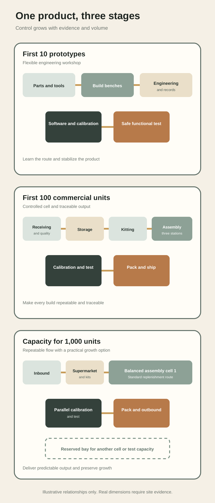
The first 10 rovers do not justify a miniature mass production line. They need a controlled engineering workshop with adaptable benches, secure components, measurement tools, software loading, calibration, and a safe functional test area. The most valuable output is learning. The team should record process steps, failures, time, tooling needs, and design changes.
The first 100 commercial units need repeatability. The layout introduces defined receiving, quarantine, kitting, point of use stock, controlled workstations, released instructions, serial records, and a separate test zone. Fixtures should remove variation where the process has stabilized. The team still needs room for engineering changes and supplier defects because the product is not yet mature.
Capacity for 1,000 units annually requires a deliberate production system. Material arrives to a supermarket, kits feed a balanced assembly cell, calibration and functional test have enough parallel capacity to avoid becoming permanent queues, and replenishment follows a standard route. The design reserves an adjacent bay for another cell or expanded test capacity. It does not install every future machine on the first day.
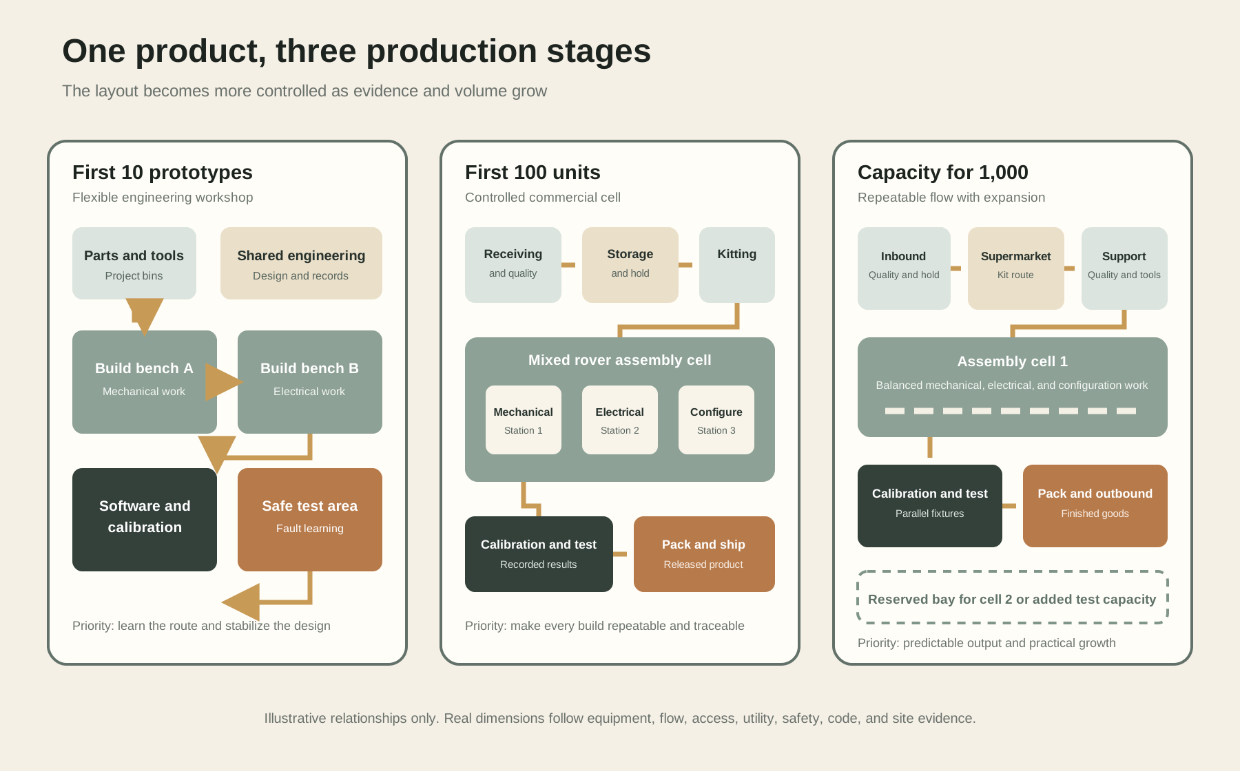
What Changes With Volume
Layout
First 10
Flexible benches around shared tools
First 100
Defined assembly cell and test area
Capacity for 1,000
Balanced flow with parallel constraints and planned replenishment
Inventory
First 10
Project bins and direct engineering control
First 100
Identified locations, quarantine, kits, and cycle counts
Capacity for 1,000
Supermarket, point of use stock, reorder logic, and supplier schedules
Quality
First 10
Engineer verifies each build
First 100
Released checks and serial records
Capacity for 1,000
Risk based incoming control, in process evidence, final release, and trend analysis
Automation
First 10
Portable tools and test scripts
First 100
Selective fixtures and assisted testing
Capacity for 1,000
Automation only where repeatability, rate, safety, or evidence justifies it
Expansion
First 10
Keep commitments reversible
First 100
Reserve utility and space interfaces
Capacity for 1,000
Add a cell or constraint resource when trigger conditions are met
| Decision | First 10 | First 100 | Capacity for 1,000 |
|---|---|---|---|
| Layout | Flexible benches around shared tools | Defined assembly cell and test area | Balanced flow with parallel constraints and planned replenishment |
| Inventory | Project bins and direct engineering control | Identified locations, quarantine, kits, and cycle counts | Supermarket, point of use stock, reorder logic, and supplier schedules |
| Quality | Engineer verifies each build | Released checks and serial records | Risk based incoming control, in process evidence, final release, and trend analysis |
| Automation | Portable tools and test scripts | Selective fixtures and assisted testing | Automation only where repeatability, rate, safety, or evidence justifies it |
| Expansion | Keep commitments reversible | Reserve utility and space interfaces | Add a cell or constraint resource when trigger conditions are met |
Learn to Read a Factory Floor Plan
A useful floor plan should answer more than where equipment sits. Begin at the receiving door and trace one normal material path. Then trace people, empty containers, waste, maintenance, visitors, emergency egress, and every expected exception. Count crossings. Look for blind corners, shared staging, blocked panels, long replenishment walks, and material that must reverse direction.
Next, inspect relationships. Receiving should connect logically to identification, incoming quality, and storage. Kitting should reach both inventory and production. Quality should be close enough to respond without becoming a hallway. Maintenance should reach equipment and spares. Packaging and finished goods should connect to shipping without sending completed product back through dirty or congested areas.
Finally, inspect the invisible layers. Where do power, compressed air, ventilation, process exhaust, cooling, drainage, network, lighting, fire protection, and security enter? Can a machine be isolated without stopping the entire plant? Can a large component be replaced? Can the roof and floor carry the loads? Can the plant operate during service? A floor plan becomes credible when it shows access and dependencies as clearly as production equipment.
A Ten Minute Floor Plan Review
Material
Look For
One direction, controlled buffers, few touches, and clear ownership
Warning Sign
Repeated crossings, backtracking, and unmarked overflow
People
Look For
Safe access to work, support, welfare, and exits
Warning Sign
Pedestrians share blind routes with lift trucks or mobile robots
Quality
Look For
Inspection at the right risk points and contained nonconforming material
Warning Sign
Failed material can reenter normal stock or bypass disposition
Maintenance
Look For
Panels, service sides, overhead access, spares, and equipment removal
Warning Sign
The machine fits but cannot be safely repaired or replaced
Utilities
Look For
Capacity, connection, isolation, drainage, exhaust, and monitoring
Warning Sign
Utility routes collide with expansion or have one fragile failure point
Emergency
Look For
Unobstructed exits, response access, alarms, and incident containment
Warning Sign
Inventory or equipment narrows paths assumed to remain open
Growth
Look For
Reserved bay, repeatable cell, utility stub, and decision trigger
Warning Sign
Future capacity exists only as an arrow beyond the property line
| Trace | Look For | Warning Sign |
|---|---|---|
| Material | One direction, controlled buffers, few touches, and clear ownership | Repeated crossings, backtracking, and unmarked overflow |
| People | Safe access to work, support, welfare, and exits | Pedestrians share blind routes with lift trucks or mobile robots |
| Quality | Inspection at the right risk points and contained nonconforming material | Failed material can reenter normal stock or bypass disposition |
| Maintenance | Panels, service sides, overhead access, spares, and equipment removal | The machine fits but cannot be safely repaired or replaced |
| Utilities | Capacity, connection, isolation, drainage, exhaust, and monitoring | Utility routes collide with expansion or have one fragile failure point |
| Emergency | Unobstructed exits, response access, alarms, and incident containment | Inventory or equipment narrows paths assumed to remain open |
| Growth | Reserved bay, repeatable cell, utility stub, and decision trigger | Future capacity exists only as an arrow beyond the property line |
Separate Flows That Should Not Meet
Efficient flow does not mean every route should be combined. Pedestrians, lift trucks, tuggers, autonomous mobile robots, visitors, hazardous material, clean components, scrap, and finished goods may need distinct paths, times, controls, or environments. Separation can be physical, procedural, scheduled, or technical, but it must be deliberate.
OSHA requires workplaces, passageways, storage rooms, service rooms, and walking surfaces to remain orderly and capable of supporting intended loads. It also requires safe access and egress. Its exit route guidance treats an exit route as a continuous and unobstructed path to safety. These are minimum regulatory boundaries, not a complete layout method. Local building and fire codes, insurer requirements, process hazards, and qualified safety analysis can impose additional constraints.
Movement rules must also survive normal pressure. If inbound material has no staging area, it will occupy an aisle. If a failed unit has no hold location, it will sit beside the test station. If packaging material has no home, it will migrate toward the shipping door. The designer should create legitimate locations for predictable states instead of relying on floor markings to defeat operational reality.
Inventory Is a Design Decision
Inventory occupies space, consumes cash, requires movement, and hides uncertainty. Too little can stop production. Too much can conceal supplier instability, quality problems, engineering changes, and weak scheduling. The correct quantity depends on replenishment time, demand variation, supplier risk, minimum order quantities, shelf life, handling requirements, and the cost of a shortage.
The plan should distinguish raw material, purchased components, line side stock, work in process, quarantined material, rework, maintenance spares, packaging, finished goods, returns, and waste. Each category needs ownership, identification, location, capacity, and a transaction rule. A generic area labeled storage is not an inventory system.
For the rover, batteries deserve special attention because chemistry, state of charge, damage, transport, fire protection, and supplier instructions can affect storage and handling. Sensitive electronics may need electrostatic controls and environmental protection. Calibrated tools and reference equipment need controlled status. Real product data must define these requirements before the facility team designs the areas.
Utilities Are Part of the Production Process
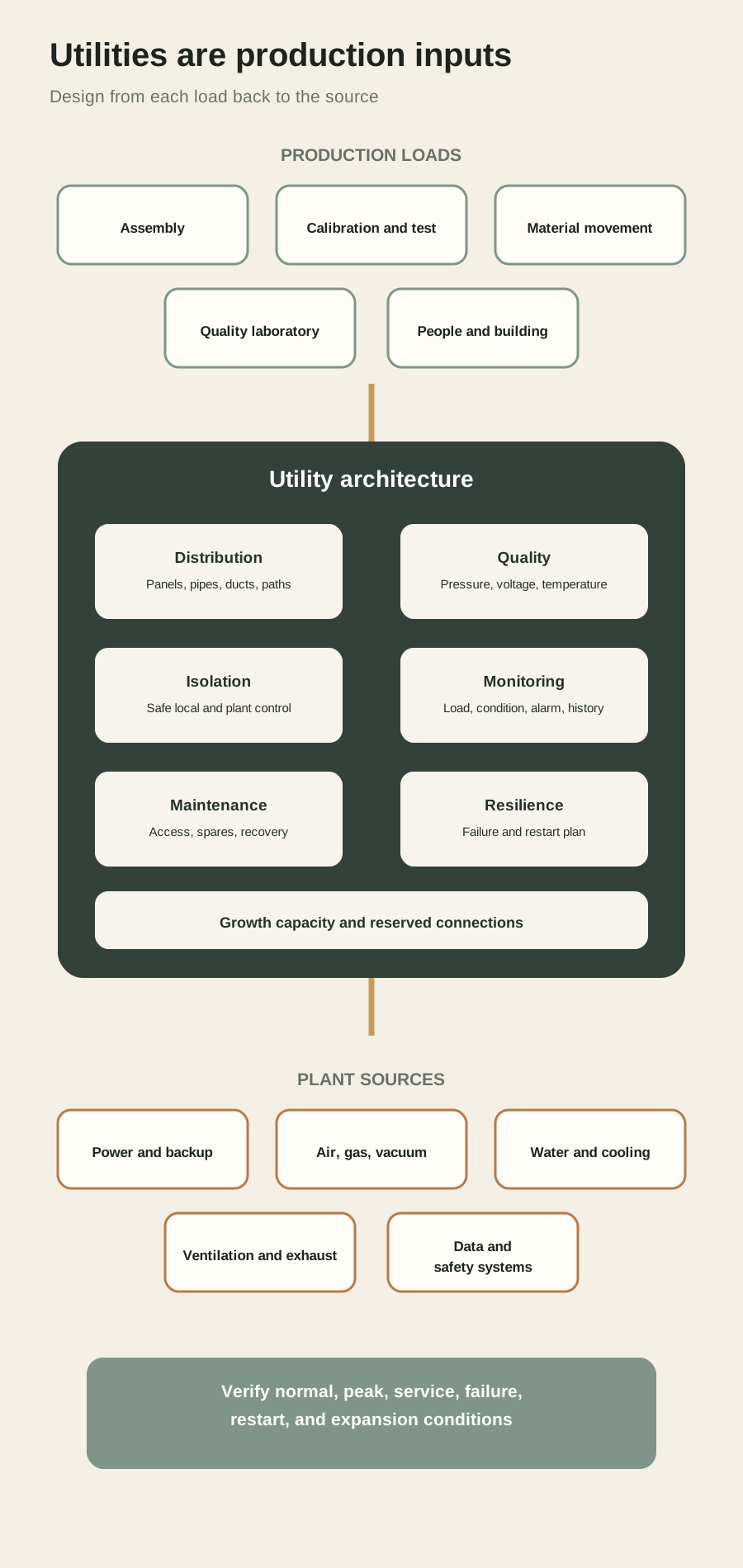
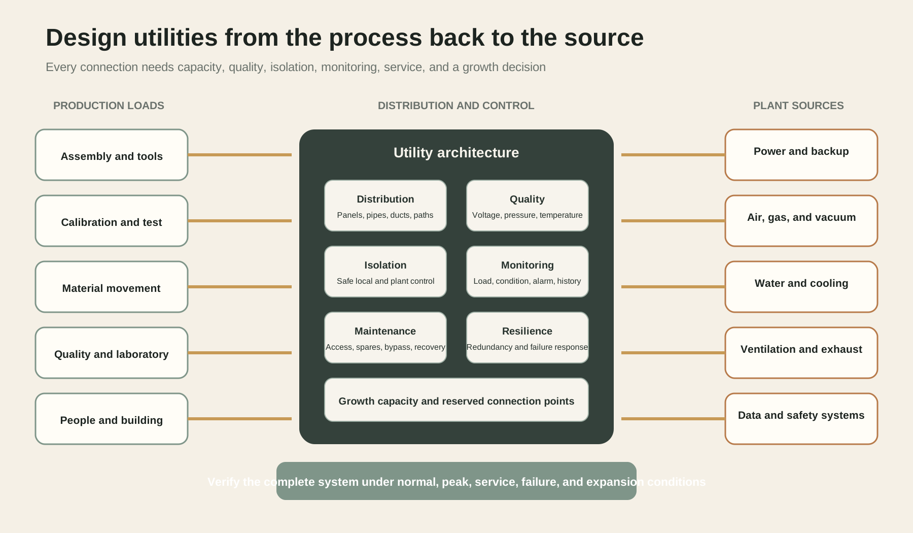
Factory utilities are not background services. They are production inputs. Electrical power can determine machine capacity and reliability. Compressed air can affect actuation, cleaning, and test. Ventilation and exhaust can protect people and product. Cooling can hold process temperature. Water quality can matter as much as water quantity. Networks carry work instructions, recipes, test records, and equipment data.
The utility schedule should begin at each load and work backward to the source. Record normal demand, peak demand, quality, pressure or voltage, temperature, redundancy, isolation, metering, maintenance access, and growth allowance. Coincidence matters because not every load peaks at once. So does startup behavior. A system that meets average demand may fail when several machines start or when a compressor, chiller, or network switch is unavailable.
DOE notes that compressed air loses more than 80 percent of its input energy as heat and recommends alternatives where possible. Its Better Plants guidance emphasizes demand reduction, lower pressure, storage and controls, leak reduction, and maintenance. This is a useful design lesson: convenient utilities can become expensive habits when the process requirement is never challenged.
Factory Utility Design Questions
Electrical
Load Questions
Voltage, phase, power, peak, startup, quality, and backup need
Layout Questions
Source, distribution, panels, isolation, clearances, cable route, and expansion
Evidence
Equipment data, load list, utility study, and licensed design
Compressed air
Load Questions
Pressure, flow, quality, duty, storage, and permitted uses
Layout Questions
Compressor room, ring or branch distribution, drops, isolation, condensate, noise, and heat
Evidence
Demand model, leakage plan, pressure study, and energy case
Ventilation and exhaust
Load Questions
Heat, particles, fumes, humidity, cleanliness, and pressure relationship
Layout Questions
Capture point, duct route, discharge, makeup air, filters, service, and zoning
Evidence
Hazard assessment, process data, industrial hygiene, and mechanical design
Cooling and water
Load Questions
Temperature, flow, quality, return, treatment, and discharge
Layout Questions
Plant loop, local chiller, drainage, spill control, meters, and maintenance
Evidence
Heat loads, water balance, discharge path, and utility confirmation
Data and controls
Load Questions
Devices, bandwidth, latency, availability, time, identity, and retention
Layout Questions
Network rooms, wired and wireless coverage, segmentation, remote access, and spare pathways
Evidence
Architecture, coverage test, cybersecurity review, and recovery plan
Fire and life safety
Load Questions
Occupancy, materials, process hazards, detection, suppression, and response
Layout Questions
Exits, access, separation, water supply, alarm, and responder access
Evidence
Code analysis, authority review, insurer input, and tested plan
| System | Load Questions | Layout Questions | Evidence |
|---|---|---|---|
| Electrical | Voltage, phase, power, peak, startup, quality, and backup need | Source, distribution, panels, isolation, clearances, cable route, and expansion | Equipment data, load list, utility study, and licensed design |
| Compressed air | Pressure, flow, quality, duty, storage, and permitted uses | Compressor room, ring or branch distribution, drops, isolation, condensate, noise, and heat | Demand model, leakage plan, pressure study, and energy case |
| Ventilation and exhaust | Heat, particles, fumes, humidity, cleanliness, and pressure relationship | Capture point, duct route, discharge, makeup air, filters, service, and zoning | Hazard assessment, process data, industrial hygiene, and mechanical design |
| Cooling and water | Temperature, flow, quality, return, treatment, and discharge | Plant loop, local chiller, drainage, spill control, meters, and maintenance | Heat loads, water balance, discharge path, and utility confirmation |
| Data and controls | Devices, bandwidth, latency, availability, time, identity, and retention | Network rooms, wired and wireless coverage, segmentation, remote access, and spare pathways | Architecture, coverage test, cybersecurity review, and recovery plan |
| Fire and life safety | Occupancy, materials, process hazards, detection, suppression, and response | Exits, access, separation, water supply, alarm, and responder access | Code analysis, authority review, insurer input, and tested plan |
Site Selection Is a Production Decision
A site should be evaluated by the complete operating case, not rent alone. The factory needs access to customers, suppliers, workforce, logistics, power, water, communications, emergency response, maintenance services, and qualified contractors. It also needs a permitting path, acceptable environmental conditions, security, resilience, and enough room for the planned life of the operation.
The weighting depends on the product. A small rover assembly plant may value technical labor, parcel and freight access, reliable power, broadband, and an adaptable light industrial building. A foundry, chemical plant, food facility, semiconductor fab, or battery plant would assign very different weight to water, wastewater, energy, emissions, process safety, geology, transport, and community impact.
Incentives should be evaluated after operational fit. A grant or tax benefit rarely rescues a site with inadequate utilities, slow permits, poor access, or an unsustainable labor model. The team should compare the present value of incentives with the cost and risk of building modifications, utility upgrades, delays, logistics, training, turnover, insurance, and future expansion.
A Practical Site Selection Scorecard
Market and supply chain
Questions
How does the site connect to customers, suppliers, ports, airports, roads, and parcel networks?
Verification
Lane data, carrier evidence, lead time, disruption alternatives, and landed cost
Workforce
Questions
Can the operation recruit, train, retain, and commute the required skills?
Verification
Labor data, local interviews, wage and benefit model, education partners, and shift access
Utilities
Questions
Are capacity, quality, reliability, lead time, and expansion available?
Verification
Written utility confirmation, outage history, upgrade scope, rate structure, and schedule
Building and land
Questions
Do structure, floor, height, docks, yard, drainage, fire protection, and expansion fit?
Verification
Survey, condition assessment, structural review, environmental diligence, and concept layout
Permits and community
Questions
Which land use, building, fire, air, water, waste, and operating approvals apply?
Verification
Qualified counsel and engineer review, authority meetings, permit matrix, and critical path
Resilience and security
Questions
How exposed is the site to weather, flood, wildfire, heat, grid, water, transport, crime, and single points of failure?
Verification
Hazard data, insurer input, emergency services, mitigation plan, and recovery scenarios
Economics
Questions
What is the complete cost to launch and operate?
Verification
Occupancy, modification, utilities, tax, logistics, labor, insurance, capital, working capital, and exit cost
| Category | Questions | Verification |
|---|---|---|
| Market and supply chain | How does the site connect to customers, suppliers, ports, airports, roads, and parcel networks? | Lane data, carrier evidence, lead time, disruption alternatives, and landed cost |
| Workforce | Can the operation recruit, train, retain, and commute the required skills? | Labor data, local interviews, wage and benefit model, education partners, and shift access |
| Utilities | Are capacity, quality, reliability, lead time, and expansion available? | Written utility confirmation, outage history, upgrade scope, rate structure, and schedule |
| Building and land | Do structure, floor, height, docks, yard, drainage, fire protection, and expansion fit? | Survey, condition assessment, structural review, environmental diligence, and concept layout |
| Permits and community | Which land use, building, fire, air, water, waste, and operating approvals apply? | Qualified counsel and engineer review, authority meetings, permit matrix, and critical path |
| Resilience and security | How exposed is the site to weather, flood, wildfire, heat, grid, water, transport, crime, and single points of failure? | Hazard data, insurer input, emergency services, mitigation plan, and recovery scenarios |
| Economics | What is the complete cost to launch and operate? | Occupancy, modification, utilities, tax, logistics, labor, insurance, capital, working capital, and exit cost |
A Building Is Not Ready Because It Is Empty
An existing building can shorten schedule, but only if its hidden conditions are understood. The due diligence team should verify legal use, property boundaries, access rights, environmental history, flood and drainage conditions, roof and envelope, structural grid, floor capacity, clear height, docks, yard circulation, fire protection, electrical service, gas, water, sewer, communications, ventilation, and the condition of major systems.
The concept layout should be placed into the candidate building before commercial commitment. Equipment must clear columns and bracing. Docks must serve the actual vehicle mix. The production route must work around exits, stairs, mechanical rooms, restrooms, and protected areas. Utility distribution and exhaust must have feasible paths. The future bay must exist in both the plan and the lease or property boundary.
Permits vary by jurisdiction and process. Building, electrical, mechanical, plumbing, fire, land use, air, wastewater, stormwater, hazardous material, and waste approvals may apply. EPA notes that specified categories of industrial activity can require stormwater permit coverage, often through an authorized state program. A permit matrix should identify the responsible party, submission basis, dependencies, review duration, inspections, and operating conditions. This report is not legal or engineering advice.
Design for Physical AI Without Designing a Fantasy
Physical AI systems need a disciplined physical environment. Mobile robots need suitable floors, routes, intersections, charging, communications, load interfaces, and recovery procedures. Vision systems need controlled views, lighting, mounting, references, and access for cleaning and calibration. Adaptive manipulation still needs stable part presentation, safe tooling, defined failure states, and a deterministic path to stop hazardous motion.
ISO 3691 Part 4 covers safety requirements and verification for driverless industrial trucks and notes that operating zone conditions significantly affect safe operation. The A3 industrial mobile robot standard family likewise addresses the robot, system, application, use, risk assessment, and management of change. The facility is therefore part of the application. Buying a mobile robot does not convert an improvised traffic pattern into a safe autonomous route.
Connectivity should also be planned as infrastructure, not added through improvised wireless coverage. Equipment identity, time synchronization, network segmentation, software distribution, data ownership, remote access, logging, and recovery need an architecture. CISA guidance treats segmentation between business and industrial control environments as a layered security measure. The precise design depends on risk, but the pathways, rooms, coverage, and ownership should exist before equipment arrives.
Future readiness does not mean installing immature technology everywhere. It can mean flat and maintainable floors, clear routes, consistent load interfaces, good lighting, spare conduit, measured utility capacity, equipment data access, accurate digital layouts, modular workstations, and room for safe trials. These features improve conventional operations even if a planned autonomous system is delayed or never purchased.
Physical AI Readiness in the Facility
Mobile material movement
Facility Condition
Stable floors, controlled intersections, defined traffic, charging, communication, and load transfer
Evidence Before Deployment
Site survey, route risk assessment, fleet study, coverage test, and recovery plan
Machine vision
Facility Condition
Repeatable view, lighting, background, mounting, protection, cleaning, and calibration access
Evidence Before Deployment
Representative image set, variation study, acceptance test, and maintenance method
Adaptive robot work
Facility Condition
Controlled task boundary, safe cell, predictable inputs, tools, fault states, and human roles
Evidence Before Deployment
Risk assessment, representative trials, integration design, and measurable acceptance
Digital twin and simulation
Facility Condition
Accurate equipment, process, layout, logic, and operating data
Evidence Before Deployment
Model purpose, validated inputs, version control, comparison to production, and named owner
AI assisted operations
Facility Condition
Trusted source data, clear decision rights, protected interfaces, and human escalation
Evidence Before Deployment
Data lineage, evaluation set, access controls, monitoring, and rollback
| Capability | Facility Condition | Evidence Before Deployment |
|---|---|---|
| Mobile material movement | Stable floors, controlled intersections, defined traffic, charging, communication, and load transfer | Site survey, route risk assessment, fleet study, coverage test, and recovery plan |
| Machine vision | Repeatable view, lighting, background, mounting, protection, cleaning, and calibration access | Representative image set, variation study, acceptance test, and maintenance method |
| Adaptive robot work | Controlled task boundary, safe cell, predictable inputs, tools, fault states, and human roles | Risk assessment, representative trials, integration design, and measurable acceptance |
| Digital twin and simulation | Accurate equipment, process, layout, logic, and operating data | Model purpose, validated inputs, version control, comparison to production, and named owner |
| AI assisted operations | Trusted source data, clear decision rights, protected interfaces, and human escalation | Data lineage, evaluation set, access controls, monitoring, and rollback |
Use Digital Models to Test Behavior
Two dimensional layout confirms whether objects fit. Three dimensional coordination can expose access, height, duct, structure, utility, and installation conflicts. Discrete event simulation can test queues, resource use, throughput, staffing, downtime, and variable arrivals over time. A digital twin may later connect the model to operating data. These are different tools with different evidence.
A simulation should answer a decision. What happens if calibration takes twenty percent longer? How much buffer protects output from a supplier delivery pattern? Does one shared test station create a queue? Can a tugger replenish two cells without blocking outbound product? Which additional resource raises accepted throughput? A colorful animation without calibrated inputs or a decision question is not validation.
The model should record assumptions, sources, versions, and confidence. Compare its output with hand calculations and observed data where possible. Test extreme conditions and equipment failures, not only the expected day. The model becomes more valuable after launch when actual process times, yields, downtime, and routes can correct the original assumptions.
Plan Expansion With Triggers and Interfaces
Expansion should be designed as a sequence of options. The launch plant may reserve an adjacent bay, electrical capacity, network pathway, utility headers, dock position, quality capacity, and a repeatable cell interface. That reservation has a cost, but it is different from buying all future equipment before demand exists.
Each phase needs a trigger. A second assembly cell might be released when the demand backlog, effective capacity, and quality stability pass defined thresholds. A second calibration station might be added earlier because it has a long lead time or creates a single point of failure. Additional inventory space might be avoided if supplier delivery frequency improves. The trigger should combine demand, process evidence, supplier lead time, installation disruption, and financial approval.
The future plan must be physically credible. A box labeled expansion is meaningless if material would have to cross shipping, the utility room is on the wrong side, the roof cannot accept new exhaust, or the lease ends before the investment pays back. The team should rehearse the next phase on the same model used for the launch plan.
Compare Designs With Total Economics
The cheapest building, shortest route, smallest footprint, and highest automation level can point to four different designs. The decision should compare service, quality, safety, resilience, flexibility, capital, operating cost, working capital, launch schedule, and downside risk. No single ratio captures the whole factory.
Installed capital includes more than equipment purchase price. It can include engineering, freight, rigging, foundations, utilities, guarding, controls, software, building modifications, permits, validation, training, spares, startup scrap, and contingency. Operating cost includes labor, occupancy, energy, maintenance, consumables, software, insurance, logistics, quality loss, and support. Inventory and the production ramp consume cash before steady output arrives.
A compact layout can reduce travel and occupancy cost, but a plan with no service access or expansion margin can create larger future expense. A flexible manual cell may beat automation at uncertain volume. A more expensive site may win if it shortens launch, supports hiring, avoids utility upgrades, and reaches suppliers and customers reliably. The economic model should preserve these tradeoffs instead of hiding them inside one square foot rate.
Factory Design Economic Boundary
Facility capital
Examples
Building work, structure, docks, offices, fire protection, HVAC, and site
Often Missed
Temporary conditions, surveys, professional fees, testing, and restoration
Production capital
Examples
Machines, fixtures, tools, inspection, handling, and automation
Often Missed
Integration, guarding, software, freight, rigging, spares, and acceptance
Utility capital
Examples
Power, air, water, cooling, exhaust, network, and metering
Often Missed
Source upgrades, redundancy, isolation, controls, and future connection points
Launch cost
Examples
Hiring, training, trial builds, validation, and production support
Often Missed
Low yield, overtime, supplier containment, engineering changes, and delayed revenue
Operating cost
Examples
Labor, occupancy, energy, maintenance, logistics, consumables, and software
Often Missed
Downtime, rework, quality escape, obsolete inventory, security, and technical support
Working capital
Examples
Raw material, work in process, finished goods, receivables, and payables
Often Missed
Minimum orders, long lead items, ramp inventory, and engineering change exposure
| Category | Examples | Often Missed |
|---|---|---|
| Facility capital | Building work, structure, docks, offices, fire protection, HVAC, and site | Temporary conditions, surveys, professional fees, testing, and restoration |
| Production capital | Machines, fixtures, tools, inspection, handling, and automation | Integration, guarding, software, freight, rigging, spares, and acceptance |
| Utility capital | Power, air, water, cooling, exhaust, network, and metering | Source upgrades, redundancy, isolation, controls, and future connection points |
| Launch cost | Hiring, training, trial builds, validation, and production support | Low yield, overtime, supplier containment, engineering changes, and delayed revenue |
| Operating cost | Labor, occupancy, energy, maintenance, logistics, consumables, and software | Downtime, rework, quality escape, obsolete inventory, security, and technical support |
| Working capital | Raw material, work in process, finished goods, receivables, and payables | Minimum orders, long lead items, ramp inventory, and engineering change exposure |
Ten Common Factory Design Mistakes
The first mistake is choosing a building before defining the route. The second is using annual demand without mix, calendar, uptime, yield, or uncertainty. The third is laying out vendor footprints without access, service, guarding, material, and utility envelopes. The fourth is optimizing normal flow while ignoring quarantine, rework, maintenance, waste, and recovery.
The fifth is treating inventory as whatever occupies the remaining floor. The sixth is assuming listed utility service equals usable capacity, quality, schedule, and resilience. The seventh is allowing pedestrians, lift equipment, and autonomous systems to inherit one ambiguous traffic pattern. The eighth is believing a simulation whose inputs have not been tested.
The ninth is buying future capacity instead of preserving practical expansion options. The tenth is treating permits, safety, environmental review, information architecture, and operating ownership as tasks that begin after the layout is complete. These subjects shape the layout from the start.
Your Factory Design Checkpoint
You should now be able to move from a product and volume target into a route, capacity model, block layout, equipment plan, utility schedule, site scorecard, and phased expansion case. You should also be able to challenge a floor plan that shows machines but not the flows, access, infrastructure, and abnormal conditions required to operate them.
The central idea is simple: a factory is designed from the production result outward. The building contains the system, but the system gives the building its purpose. Good plant design makes normal work clear, exceptions controllable, maintenance possible, growth credible, and future technology optional rather than compulsory.
Five Questions You Should Now Be Able to Answer
What should be designed first?
What a Good Answer Contains
Accepted product, demand cases, route, capacity, quality, inventory, and make versus buy decisions
Which layout fits the work?
What a Good Answer Contains
A reasoned choice among process, product, cellular, fixed position, or a hybrid
How do you test a floor plan?
What a Good Answer Contains
Trace every flow, inspect relationships, verify access and utilities, and challenge abnormal conditions
How do you compare sites?
What a Good Answer Contains
Operational fit, verified utilities, workforce, logistics, permits, resilience, complete economics, and expansion
What makes a factory ready for physical AI?
What a Good Answer Contains
Stable process, safe geometry, good lighting, controlled traffic, connectivity, data, interfaces, and recovery
| Question | What a Good Answer Contains |
|---|---|
| What should be designed first? | Accepted product, demand cases, route, capacity, quality, inventory, and make versus buy decisions |
| Which layout fits the work? | A reasoned choice among process, product, cellular, fixed position, or a hybrid |
| How do you test a floor plan? | Trace every flow, inspect relationships, verify access and utilities, and challenge abnormal conditions |
| How do you compare sites? | Operational fit, verified utilities, workforce, logistics, permits, resilience, complete economics, and expansion |
| What makes a factory ready for physical AI? | Stable process, safe geometry, good lighting, controlled traffic, connectivity, data, interfaces, and recovery |
Next in the Series
Part 6 will open the factory nervous system. We will start with the control loop and connect sensors, actuators, motors, drives, programmable controllers, safety controllers, human machine interfaces, computer numerical control, industrial networks, robots, and the factory software stack.
The rover plant will return as the working environment. One production order will move from business planning into scheduled work, machine and operator instructions, physical action, inspection evidence, and the production record. The goal will be to understand which decisions require deterministic control and where perception, learning, planning, and adaptation can safely add value.
Research Method
This report uses NIST factory design, production system, manufacturing readiness, value stream, and Manufacturing Extension Partnership materials for the design sequence, flow, layout, and verification framework. DOE Better Plants materials support the utility discussion. OSHA materials support general walking surface, access, and exit route boundaries. EPA materials support the permitting examples.
ISO and the Association for Advancing Automation provide the current industrial mobile robot safety context. CISA provides the network segmentation context. Autodesk factory design materials illustrate the distinction between spatial layout and dynamic operational simulation. Vendor materials describe capabilities and workflows, not independently verified performance for the hypothetical rover factory.
The rover route, volumes, layouts, space relationships, capacity examples, scorecards, economic boundaries, and expansion triggers are Black Scarab teaching frameworks. They do not describe a real factory, quoted project, legal requirement, guaranteed output, or recommended investment. Facility design requires qualified manufacturing, architecture, engineering, safety, environmental, cybersecurity, insurance, commercial, and legal review for the actual site and jurisdiction.
Continue the series
Inside the Physical AI FactoryPart 5 of 8

About the author
Rodolfo Garcia Calderoni, CFA
Rodolfo is the founder of Black Scarab, where he covers the technologies and commercial signals shaping physical AI adoption.
Meet RodolfoBlack Scarab Weekly
Catch up on physical AI in one email
Every new Black Scarab deep dive and news report, collected into one clear Thursday briefing.
Related Insights
Manufacturing
Who Builds a Factory? Siemens, Rockwell, FANUC, Machine Builders, and Integrators Explained
A practical map of the companies behind industrial production, from equipment and controls suppliers to machine builders, integrators, engineering firms, contractors, software providers, and contract manufacturers.
Read related insight
Manufacturing
How a Product Is Manufactured: From Bill of Materials to Production Line
A worked manufacturing plan for an autonomous inspection rover, from product architecture and supplier choices to routing, quality, cost, and capacity for the first 1,000 units.
Read related insight
Manufacturing
Types of Manufacturing Machines: A Beginner's Guide to Factory Equipment
A visual machine atlas covering how factory equipment removes, forms, adds, molds, casts, joins, assembles, inspects, moves, and packages material.
Read related insight
Next Step
Explore a commercial opportunity in Mexico
If you are exploring how a physical AI technology could fit the Mexican market, Black Scarab can help assess the opportunity, map relevant stakeholders, and define a credible commercial next step.