Inside the Physical AI Factory · Part 3 of 8
How a Product Is Manufactured: From Bill of Materials to Production Line
A worked manufacturing plan for an autonomous inspection rover, from product architecture and supplier choices to routing, quality, cost, and capacity for the first 1,000 units.
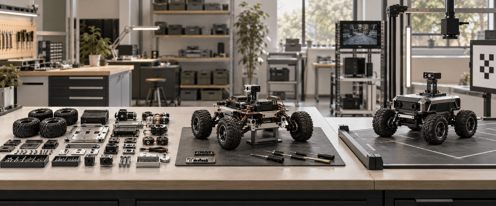
This is Part 3 of Inside the Physical AI Factory. Part 1 mapped the factory. Part 2 mapped the machines. Now we connect product, parts, suppliers, operations, people, and evidence into one route that can produce an accepted unit repeatedly.
A prototype can work even when its manufacturing system does not. An engineer may spend a day adjusting a bracket, replace an unavailable connector, hand route a cable, load software from a laptop, and remember the one unusual calibration step. The finished rover moves. The knowledge required to build it again still lives in the engineer rather than in a controlled production process.
Manufacturing begins when that hidden knowledge becomes explicit. The product needs a released definition. Every item needs an identity, quantity, source, revision, and acceptance requirement. Every operation needs an input, output, sequence, resource, time assumption, and response to failure. The route must produce the same approved configuration without depending on memory or improvisation.
This report builds that system around the hypothetical autonomous inspection rover used throughout the series. We will take it apart, construct a bill of materials, map representative suppliers, choose what to make and buy, write the production route, and compare ten prototypes, the first one hundred commercial units, and capacity for one thousand units per year. All rover specifications, costs, labor times, yields, and volumes are illustrative planning assumptions. They do not describe a real product or supplier relationship.
A Manufactured Product in One Sentence
Requirements, drawings, software, bill of materials, approved sources, and test criteria
Production System
A controlled route of purchasing, fabrication, assembly, programming, inspection, and records
Accepted Result
A traceable unit that conforms to its released configuration and performs its intended job
| Product Definition | Production System | Accepted Result |
|---|---|---|
| Requirements, drawings, software, bill of materials, approved sources, and test criteria | A controlled route of purchasing, fabrication, assembly, programming, inspection, and records | A traceable unit that conforms to its released configuration and performs its intended job |
The Product Is More Than Its Shape
A three dimensional model may define the geometry of a bracket, but it does not define the complete product. Production also needs materials, finishes, tolerances, purchased part numbers, electrical drawings, cable definitions, software versions, calibration data, labels, packaging, inspection methods, and approved deviations. The build package must answer what to make, what to buy, how the pieces connect, and how acceptance will be proven.
NASA describes approved specifications, drawings, parts lists, and other configuration documentation as the baseline of a product. Its configuration management guidance focuses on keeping the physical product and its information consistent as changes occur. The underlying lesson applies far beyond aerospace. If the drawing says revision C, the work instruction says revision B, and the purchasing system orders the revision A component, the factory does not have one product definition.
The digital thread is the connection among these records. NIST describes it as lifecycle information linking design, manufacturing, quality, and product support. For the rover, a failed camera alignment test should point to the unit serial number, camera lot, bracket revision, fixture version, calibration procedure, result, and corrective action. That chain turns a defect into usable engineering feedback rather than an isolated surprise.
The Minimum Production Definition
Requirements
Question It Answers
What must the product do and withstand?
Rover Example
Inspection mission, operating environment, safety behavior, runtime, and interfaces
Engineering drawings and models
Question It Answers
What is the approved geometry and material?
Rover Example
Frame, enclosure, wheel hub, sensor bracket, and gasket definitions
Bill of materials
Question It Answers
What items and quantities form one shippable unit?
Rover Example
Motors, gearboxes, battery, boards, cameras, harnesses, fasteners, labels, and packaging
Software configuration
Question It Answers
Which code, model, settings, and credentials belong on the unit?
Rover Example
Boot image, motor control firmware, perception model, calibration file, and release identifier
Process plan
Question It Answers
Which operations transform the inputs?
Rover Example
Receive, kit, assemble, wire, program, calibrate, test, and pack
Quality plan
Question It Answers
What is checked, when, by whom, and against which limit?
Rover Example
Incoming evidence, torque records, continuity, calibration, braking, navigation, and final audit
Change record
Question It Answers
Why did the baseline change and where was it applied?
Rover Example
New connector, revised bracket, alternate camera, updated model, or corrected work instruction
| Record | Question It Answers | Rover Example |
|---|---|---|
| Requirements | What must the product do and withstand? | Inspection mission, operating environment, safety behavior, runtime, and interfaces |
| Engineering drawings and models | What is the approved geometry and material? | Frame, enclosure, wheel hub, sensor bracket, and gasket definitions |
| Bill of materials | What items and quantities form one shippable unit? | Motors, gearboxes, battery, boards, cameras, harnesses, fasteners, labels, and packaging |
| Software configuration | Which code, model, settings, and credentials belong on the unit? | Boot image, motor control firmware, perception model, calibration file, and release identifier |
| Process plan | Which operations transform the inputs? | Receive, kit, assemble, wire, program, calibrate, test, and pack |
| Quality plan | What is checked, when, by whom, and against which limit? | Incoming evidence, torque records, continuity, calibration, braking, navigation, and final audit |
| Change record | Why did the baseline change and where was it applied? | New connector, revised bracket, alternate camera, updated model, or corrected work instruction |
Black Scarab Weekly
Get the next Black Scarab deep dive
Keep reading now, then get every new deep dive and news report in Thursday's briefing.
Take the Rover Apart Before Planning the Factory
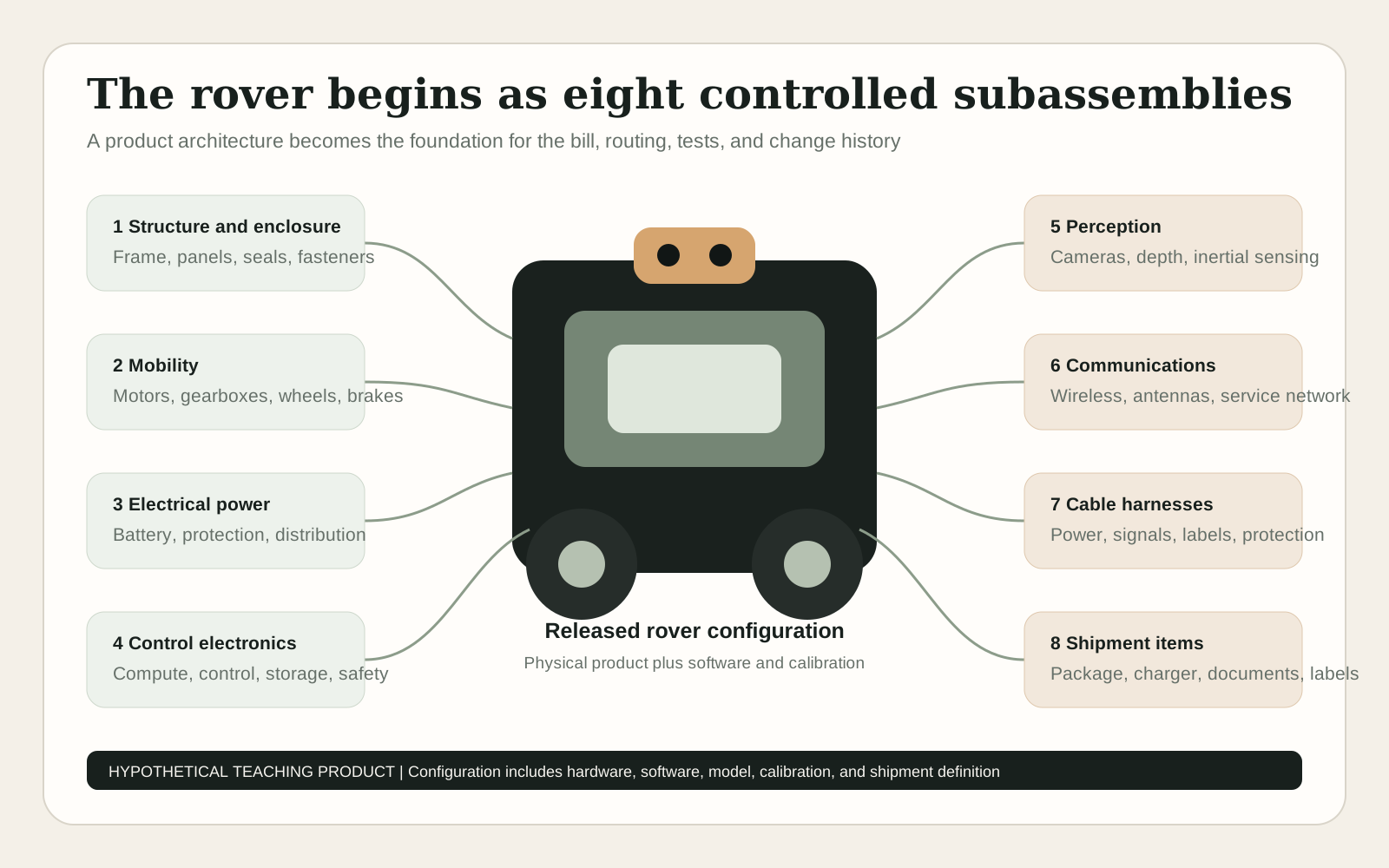
A useful bill of materials follows product structure. The top level rover contains major subassemblies that can be designed, purchased, assembled, inspected, and changed with clear boundaries. Each subassembly then contains lower level parts. This hierarchy helps engineering manage interfaces and helps production decide where work should happen.
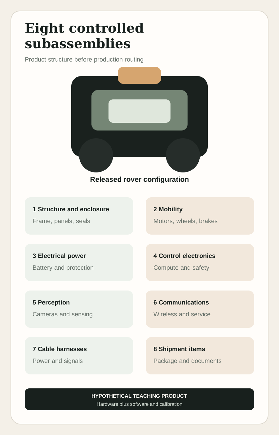
The teaching rover uses eight major groups: structure and enclosure, mobility, electrical power, control electronics, perception, communications, cable harnesses, and shipment items. Software and calibration are configuration items even though they are not physical inventory. Fixtures, tools, spare consumables, and factory test equipment belong to the manufacturing system rather than the sellable product bill.
Interfaces deserve special attention because defects collect where subsystems meet. A motor may pass its supplier test while the rover fails because the gearbox ratio, wheel diameter, encoder convention, motor controller settings, cable pinout, and software sign convention do not agree. Product architecture is therefore also an integration plan.
Illustrative Rover Product Structure
Structure and enclosure
Representative Contents
Frame, panels, covers, brackets, seals, and fasteners
Critical Interfaces
Mounting datums, stiffness, clearances, grounding, and environmental sealing
Acceptance Focus
Dimensions, finish, thread condition, fit, and sealing surfaces
Mobility
Representative Contents
Motors, gearboxes, wheels, hubs, bearings, encoders, and brakes
Critical Interfaces
Mechanical mounting, shaft connection, power, feedback, and control direction
Acceptance Focus
Free rotation, alignment, backlash, encoder response, and braking
Electrical power
Representative Contents
Battery pack, battery management, protection, contactor, charging port, and distribution
Critical Interfaces
Voltage, current, grounding, thermal path, communication, and safe isolation
Acceptance Focus
Identity, polarity, insulation, protection behavior, and charge function
Control electronics
Representative Contents
Embedded computer, carrier board, motor controllers, safety controller, and storage
Critical Interfaces
Power rails, networks, input and output, timing, and software compatibility
Acceptance Focus
Correct revision, firmware, communication, thermal contact, and functional input and output
Perception
Representative Contents
Cameras, depth sensors, illumination, inertial sensing, and protective windows
Critical Interfaces
Field of view, mounting, time synchronization, compute, calibration, and cleaning
Acceptance Focus
Image quality, alignment, timestamps, calibration, and occlusion
Communications
Representative Contents
Wireless module, antennas, service port, and internal network components
Critical Interfaces
Radio region, antenna placement, network identity, cybersecurity, and service access
Acceptance Focus
Connectivity, configuration, identity, and permitted transmit behavior
Cable harnesses
Representative Contents
Power cables, signal harnesses, connectors, labels, clips, and protective sleeving
Critical Interfaces
Pinout, bend radius, retention, routing, abrasion, and service loops
Acceptance Focus
Continuity, insulation, pull security, labeling, and routing
Shipment items
Representative Contents
Protective packaging, charger, accessories, documentation, and serial label
Critical Interfaces
Configuration match, battery shipping rules, customer setup, and transport protection
Acceptance Focus
Pack audit, label match, accessory count, and package integrity
| Subassembly | Representative Contents | Critical Interfaces | Acceptance Focus |
|---|---|---|---|
| Structure and enclosure | Frame, panels, covers, brackets, seals, and fasteners | Mounting datums, stiffness, clearances, grounding, and environmental sealing | Dimensions, finish, thread condition, fit, and sealing surfaces |
| Mobility | Motors, gearboxes, wheels, hubs, bearings, encoders, and brakes | Mechanical mounting, shaft connection, power, feedback, and control direction | Free rotation, alignment, backlash, encoder response, and braking |
| Electrical power | Battery pack, battery management, protection, contactor, charging port, and distribution | Voltage, current, grounding, thermal path, communication, and safe isolation | Identity, polarity, insulation, protection behavior, and charge function |
| Control electronics | Embedded computer, carrier board, motor controllers, safety controller, and storage | Power rails, networks, input and output, timing, and software compatibility | Correct revision, firmware, communication, thermal contact, and functional input and output |
| Perception | Cameras, depth sensors, illumination, inertial sensing, and protective windows | Field of view, mounting, time synchronization, compute, calibration, and cleaning | Image quality, alignment, timestamps, calibration, and occlusion |
| Communications | Wireless module, antennas, service port, and internal network components | Radio region, antenna placement, network identity, cybersecurity, and service access | Connectivity, configuration, identity, and permitted transmit behavior |
| Cable harnesses | Power cables, signal harnesses, connectors, labels, clips, and protective sleeving | Pinout, bend radius, retention, routing, abrasion, and service loops | Continuity, insulation, pull security, labeling, and routing |
| Shipment items | Protective packaging, charger, accessories, documentation, and serial label | Configuration match, battery shipping rules, customer setup, and transport protection | Pack audit, label match, accessory count, and package integrity |
The architecture is a teaching example. It is not a released rover specification and does not imply that every real inspection robot uses these components.
Build a Bill of Materials That Purchasing Can Use
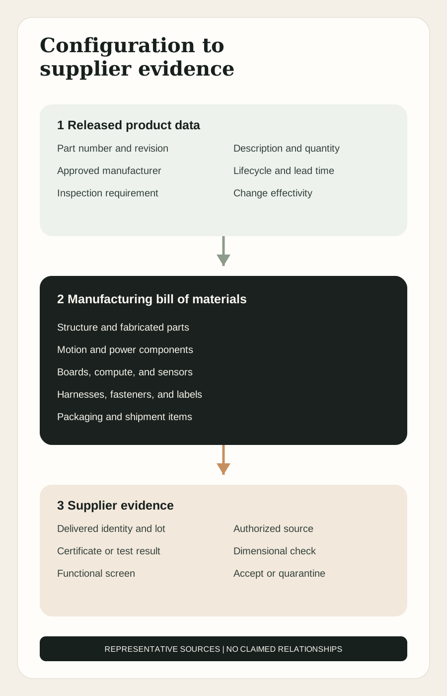
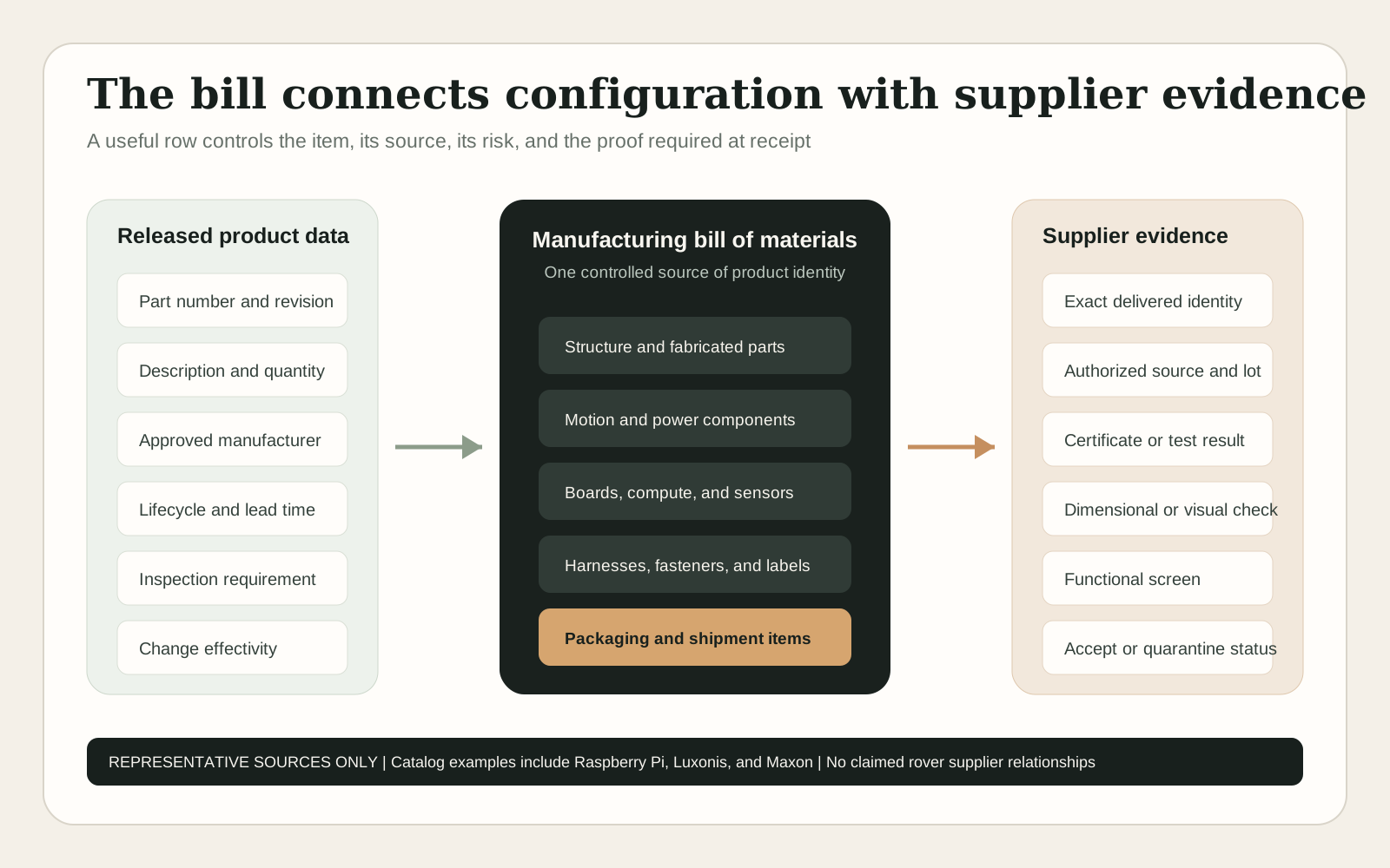
A bill of materials is often introduced as an ingredients list. Production needs more than item names and quantities. Each row should identify the internal part number, description, revision, quantity, unit of measure, make or buy status, approved manufacturer and supplier information, lifecycle risk, lead time assumption, inspection requirement, and the assembly in which the item is consumed.
The engineering bill of materials explains the designed product. The manufacturing bill adds what is needed to build and ship it through the chosen route. A design may show one cable assembly. The manufacturing record may also need labels, tie points, protective sleeving, consumable allowance, test adapters, and the sequence in which branches are installed. Packaging and included accessories belong in the shippable product definition even when they are absent from the engineering model.
IPC's production checklist identifies the bill of materials alongside board data, fabrication notes, assembly notes, drawings, and other engineering documentation. Its design for manufacturing guidance also shows why a board file alone is not enough. The manufacturer must be able to compare the design with process capability before material is committed.
Public catalog examples show how quickly a provisional choice becomes configuration data. Raspberry Pi currently offers Compute Module 5 in multiple memory, storage, and wireless variants, with official product documentation and lifecycle information. Luxonis lists several OAK camera configurations with different optics, enclosures, interfaces, and public prices. Writing only Compute Module or depth camera in a bill of materials would not control what arrives, what fits, or what software image should be loaded.
Illustrative Bill of Materials Extract
Welded or bolted frame assembly
Quantity
1
Source Strategy
Fabricate from released drawing through a qualified local supplier
Production Record
Drawing revision, material certificate where required, dimensional report, and finish record
Main Risk
Distortion, datum error, late design change, or supplier capacity
Drive motor and gearbox assembly
Quantity
4
Source Strategy
Buy configured motion assemblies from an approved manufacturer or distributor
Production Record
Exact manufacturer part number, ratio, encoder, connector, and lot
Main Risk
Single source, long lead time, or interface change
Battery pack with management system
Quantity
1
Source Strategy
Buy a documented pack or engage a qualified pack supplier
Production Record
Configuration, safety documentation, lot, state at receipt, and test evidence
Main Risk
Transport, cell change, certification boundary, thermal design, or obsolescence
Embedded compute module
Quantity
1
Source Strategy
Buy an exact released variant through authorized channels
Production Record
Memory, storage, wireless option, serial identity, and software compatibility
Main Risk
Allocation, silent substitution, lifecycle, or regional radio configuration
Custom carrier board assembly
Quantity
1
Source Strategy
Outsource board fabrication and assembly from released production data
Production Record
Board revision, assembly revision, approved parts, test result, and rework history
Main Risk
Component shortage, footprint error, workmanship, or untested substitution
Depth camera assembly
Quantity
1
Source Strategy
Buy a selected catalog device or qualified custom module
Production Record
Exact model, firmware, calibration identity, cable, and incoming function
Main Risk
Field of view, environmental limit, interface, or supplier revision
Main cable harness set
Quantity
1
Source Strategy
Build internally for prototypes, then outsource to released drawings and test requirements
Production Record
Harness revision, connector and terminal identity, continuity result, and operator or supplier lot
Main Risk
Pinout error, incorrect crimp, routing conflict, or uncontrolled alternate
Final package set
Quantity
1
Source Strategy
Buy converted packaging to a released specification
Production Record
Package revision, included accessories, labels, and pack audit
Main Risk
Transit damage, missing accessory, battery marking, or version mismatch
| Item | Quantity | Source Strategy | Production Record | Main Risk |
|---|---|---|---|---|
| Welded or bolted frame assembly | 1 | Fabricate from released drawing through a qualified local supplier | Drawing revision, material certificate where required, dimensional report, and finish record | Distortion, datum error, late design change, or supplier capacity |
| Drive motor and gearbox assembly | 4 | Buy configured motion assemblies from an approved manufacturer or distributor | Exact manufacturer part number, ratio, encoder, connector, and lot | Single source, long lead time, or interface change |
| Battery pack with management system | 1 | Buy a documented pack or engage a qualified pack supplier | Configuration, safety documentation, lot, state at receipt, and test evidence | Transport, cell change, certification boundary, thermal design, or obsolescence |
| Embedded compute module | 1 | Buy an exact released variant through authorized channels | Memory, storage, wireless option, serial identity, and software compatibility | Allocation, silent substitution, lifecycle, or regional radio configuration |
| Custom carrier board assembly | 1 | Outsource board fabrication and assembly from released production data | Board revision, assembly revision, approved parts, test result, and rework history | Component shortage, footprint error, workmanship, or untested substitution |
| Depth camera assembly | 1 | Buy a selected catalog device or qualified custom module | Exact model, firmware, calibration identity, cable, and incoming function | Field of view, environmental limit, interface, or supplier revision |
| Main cable harness set | 1 | Build internally for prototypes, then outsource to released drawings and test requirements | Harness revision, connector and terminal identity, continuity result, and operator or supplier lot | Pinout error, incorrect crimp, routing conflict, or uncontrolled alternate |
| Final package set | 1 | Buy converted packaging to a released specification | Package revision, included accessories, labels, and pack audit | Transit damage, missing accessory, battery marking, or version mismatch |
The table defines information needs, not actual purchasing commitments. Supplier qualification must match the product, market, safety case, and jurisdiction.
Make Versus Buy Is a Capability Decision
The make versus buy decision should not begin with the price of one part. It should begin with the capability required to deliver the part repeatedly. Owning a process means owning its equipment, people, safety, quality, maintenance, scheduling, materials, waste, data, and recovery when something fails. Buying the part means owning the specification, supplier selection, incoming evidence, change control, commercial terms, and contingency plan.
For ten rovers, outsourced laser cutting, machining, board assembly, battery packs, and cable fabrication can provide capabilities that would be irrational to build. Internal work can focus on integration, software, fixtures, calibration, and learning. At one hundred units, recurring lead time and quality problems may justify bringing selected harness, fixture, or final assembly work inside. At one thousand units, a stable and heavily used process may justify dedicated equipment, but volume alone does not make every process strategic.
The product boundary matters. A startup can own the design, software, final integration, test records, and customer support while buying nearly every component and fabricated part. That is still a manufacturer if it controls the product configuration and accepts responsibility for the finished result. Outsourcing transfers work. It does not transfer product accountability.
Rover Make Versus Buy Decisions by Stage
Frame and sheet fabrication
10 Prototypes
Outsource flexible processes
100 Units
Outsource with fixtures and agreed inspection
1,000 Unit Capacity
Compete qualified suppliers against an internal cell only if utilization supports it
Reasoning
Specialized machines, finishing, and skilled fabrication are available externally
Printed circuit board assembly
10 Prototypes
Outsource prototypes
100 Units
Outsource controlled batches
1,000 Unit Capacity
Outsource recurring production with test coverage and alternate planning
Reasoning
Electronics assembly requires process control, capital, material handling, and inspection beyond a pick and place machine
Cable harnesses
10 Prototypes
Build or modify internally to learn
100 Units
Use a qualified supplier for released harnesses while retaining rapid repair capability
1,000 Unit Capacity
Outsource stable volume or own a dedicated documented cell
Reasoning
Harnesses are labor intensive and defect sensitive, but early revisions change often
Final mechanical and electrical assembly
10 Prototypes
Own the learning
100 Units
Own or supervise a flexible assembly cell
1,000 Unit Capacity
Own the final route or place it with a contract manufacturer under strong configuration control
Reasoning
Integration captures cross subsystem defects and product knowledge
Software loading and calibration
10 Prototypes
Own
100 Units
Own
1,000 Unit Capacity
Own the process definition, data, release authority, and audit trail even if a partner operates the station
Reasoning
Software identity and calibration determine the actual behavior of the physical product
Environmental and specialized compliance testing
10 Prototypes
Use external laboratories
100 Units
Use external laboratories for qualification and selected audits
1,000 Unit Capacity
Combine internal screening with external certification and surveillance as required
Reasoning
Rare equipment and independent evidence favor qualified laboratories
| Capability | 10 Prototypes | 100 Units | 1,000 Unit Capacity | Reasoning |
|---|---|---|---|---|
| Frame and sheet fabrication | Outsource flexible processes | Outsource with fixtures and agreed inspection | Compete qualified suppliers against an internal cell only if utilization supports it | Specialized machines, finishing, and skilled fabrication are available externally |
| Printed circuit board assembly | Outsource prototypes | Outsource controlled batches | Outsource recurring production with test coverage and alternate planning | Electronics assembly requires process control, capital, material handling, and inspection beyond a pick and place machine |
| Cable harnesses | Build or modify internally to learn | Use a qualified supplier for released harnesses while retaining rapid repair capability | Outsource stable volume or own a dedicated documented cell | Harnesses are labor intensive and defect sensitive, but early revisions change often |
| Final mechanical and electrical assembly | Own the learning | Own or supervise a flexible assembly cell | Own the final route or place it with a contract manufacturer under strong configuration control | Integration captures cross subsystem defects and product knowledge |
| Software loading and calibration | Own | Own | Own the process definition, data, release authority, and audit trail even if a partner operates the station | Software identity and calibration determine the actual behavior of the physical product |
| Environmental and specialized compliance testing | Use external laboratories | Use external laboratories for qualification and selected audits | Combine internal screening with external certification and surveillance as required | Rare equipment and independent evidence favor qualified laboratories |
The Routing Tells the Product Where to Go
The bill of materials says what belongs in the rover. The routing says how one accepted rover is produced. Each operation should identify the work center, predecessor, standard input, instructions, tools or fixtures, expected time, quality gate, output status, and record created. A route can include outside supplier operations as well as internal work.
The route should follow physical and verification logic. Hidden joints are checked before they are covered. Electrical continuity is tested before expensive electronics are connected. A software image is verified before calibration. Subsystems are tested before final integration when that makes fault isolation cheaper. The final functional test proves the released unit, not just a collection of passing parts.
NASA separates verification from validation. Verification asks whether the product conforms to its requirements. Validation asks whether it performs the intended purpose in the intended environment. A rover can pass dimensional, electrical, software, and braking requirements yet still fail to complete a representative inspection mission. Production acceptance needs both the build requirements and an appropriate operational demonstration.
Illustrative Rover Production Route
Receive and identify
Input
Purchased and fabricated items
Work
Match part, revision, quantity, condition, and required supplier evidence
Quality Gate
Accept, quarantine, or reject against purchase and inspection requirements
Output Record
Receipt lot and status
Kit one unit
Input
Released bill and available inventory
Work
Collect verified parts by serial, lot, or quantity and stage shortages visibly
Quality Gate
Independent kit check for critical and similar looking items
Output Record
Kit identity and shortage list
Build structure
Input
Frame, panels, inserts, seals, and fasteners
Work
Assemble in a fixture and record controlled joints
Quality Gate
Datums, clearances, thread condition, torque where required, and visual acceptance
Output Record
Structure serial and assembly record
Install mobility
Input
Motor, gearbox, wheel, hub, encoder, brake, and cables
Work
Mount, align, connect, and establish direction conventions
Quality Gate
Free rotation, current response, encoder direction, brake action, and clearance
Output Record
Mobility test result
Install power and controls
Input
Battery, protection, distribution, boards, compute, and safety components
Work
Mount with controlled thermal, electrical, and grounding interfaces
Quality Gate
Polarity, insulation, ground, connector lock, power rail, and safe state checks
Output Record
Electrical build and test record
Install perception and communications
Input
Cameras, inertial sensor, antennas, windows, mounts, and network cables
Work
Mount to controlled datums and protect optical paths
Quality Gate
Identity, image, network, placement, visibility, and mechanical retention
Output Record
Sensor identity map
Load software
Input
Released image, firmware, model, settings, and device credentials
Work
Program the unit through a controlled station
Quality Gate
Cryptographic or recorded release identity, successful boot, and correct device configuration
Output Record
Software manifest linked to unit serial
Calibrate
Input
Complete powered rover and calibrated fixture
Work
Estimate sensor, wheel, and motion parameters under controlled conditions
Quality Gate
Values within defined limits and calibration data saved to the correct unit
Output Record
Calibration file and station version
Final verification and validation
Input
Released configured rover
Work
Run safety, communications, mobility, perception, charging, and representative mission checks
Quality Gate
All required results pass, exceptions are closed, and the exact configuration is captured
Output Record
Final acceptance record
Pack and release
Input
Accepted rover, accessories, labels, documents, and package
Work
Protect, identify, audit, seal, and transfer to finished goods
Quality Gate
Serial, software, accessories, battery state, package revision, and shipment data agree
Output Record
Pack audit and release status
| Operation | Input | Work | Quality Gate | Output Record |
|---|---|---|---|---|
| Receive and identify | Purchased and fabricated items | Match part, revision, quantity, condition, and required supplier evidence | Accept, quarantine, or reject against purchase and inspection requirements | Receipt lot and status |
| Kit one unit | Released bill and available inventory | Collect verified parts by serial, lot, or quantity and stage shortages visibly | Independent kit check for critical and similar looking items | Kit identity and shortage list |
| Build structure | Frame, panels, inserts, seals, and fasteners | Assemble in a fixture and record controlled joints | Datums, clearances, thread condition, torque where required, and visual acceptance | Structure serial and assembly record |
| Install mobility | Motor, gearbox, wheel, hub, encoder, brake, and cables | Mount, align, connect, and establish direction conventions | Free rotation, current response, encoder direction, brake action, and clearance | Mobility test result |
| Install power and controls | Battery, protection, distribution, boards, compute, and safety components | Mount with controlled thermal, electrical, and grounding interfaces | Polarity, insulation, ground, connector lock, power rail, and safe state checks | Electrical build and test record |
| Install perception and communications | Cameras, inertial sensor, antennas, windows, mounts, and network cables | Mount to controlled datums and protect optical paths | Identity, image, network, placement, visibility, and mechanical retention | Sensor identity map |
| Load software | Released image, firmware, model, settings, and device credentials | Program the unit through a controlled station | Cryptographic or recorded release identity, successful boot, and correct device configuration | Software manifest linked to unit serial |
| Calibrate | Complete powered rover and calibrated fixture | Estimate sensor, wheel, and motion parameters under controlled conditions | Values within defined limits and calibration data saved to the correct unit | Calibration file and station version |
| Final verification and validation | Released configured rover | Run safety, communications, mobility, perception, charging, and representative mission checks | All required results pass, exceptions are closed, and the exact configuration is captured | Final acceptance record |
| Pack and release | Accepted rover, accessories, labels, documents, and package | Protect, identify, audit, seal, and transfer to finished goods | Serial, software, accessories, battery state, package revision, and shipment data agree | Pack audit and release status |
Ten Prototypes Buy Knowledge
The first ten units should not pretend to be a mature line. Their purpose is to expose interface errors, difficult assembly steps, weak parts, missing requirements, test gaps, supplier limitations, and the real sequence of work. Flexibility is more valuable than local efficiency because the design is still moving.
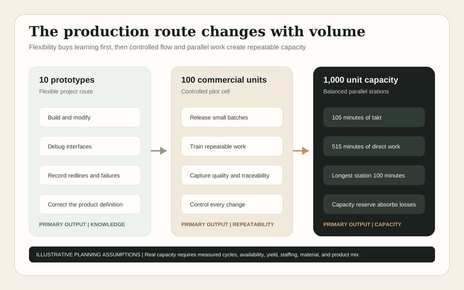
Prototype parts may be machined from stock, printed, laser cut, or assembled from development modules. Harnesses may be made on a bench. Engineers may perform most of the integration. That is acceptable only when every workaround becomes visible. Redlines, substitutions, rework, calibration changes, and failures must return to the released definition or be closed before the next build.
The most useful output is not ten matching shells. It is a more complete production package. The team should finish the build with corrected drawings, a structured bill of materials, known supplier questions, preliminary work instructions, repeatable test methods, a defect record, and evidence about which design decisions are ready to freeze.
What to Learn From Ten Prototypes
Does every interface fit and function?
Evidence to Capture
Actual dimensions, assembly interference, connector access, cable routing, thermal contact, and software integration
Decision Before the Next Stage
Correct the design or formally accept the interface
Can another person build it?
Evidence to Capture
Observed build sequence, questions, mistakes, tool access, and time by operation
Decision Before the Next Stage
Create usable instructions and simplify ambiguous work
Can requirements be tested?
Evidence to Capture
Test setup, repeatability, failures, false failures, and missing limits
Decision Before the Next Stage
Release preliminary acceptance methods and fixtures
Can the parts be sourced again?
Evidence to Capture
Supplier quote, lead time, minimum quantity, lifecycle, alternates, and change notice process
Decision Before the Next Stage
Approve sources and identify redesign risk
Which choices should remain flexible?
Evidence to Capture
Failure severity, learning rate, customer feedback, and cost of future change
Decision Before the Next Stage
Freeze only the interfaces required to proceed
| Learning Question | Evidence to Capture | Decision Before the Next Stage |
|---|---|---|
| Does every interface fit and function? | Actual dimensions, assembly interference, connector access, cable routing, thermal contact, and software integration | Correct the design or formally accept the interface |
| Can another person build it? | Observed build sequence, questions, mistakes, tool access, and time by operation | Create usable instructions and simplify ambiguous work |
| Can requirements be tested? | Test setup, repeatability, failures, false failures, and missing limits | Release preliminary acceptance methods and fixtures |
| Can the parts be sourced again? | Supplier quote, lead time, minimum quantity, lifecycle, alternates, and change notice process | Approve sources and identify redesign risk |
| Which choices should remain flexible? | Failure severity, learning rate, customer feedback, and cost of future change | Freeze only the interfaces required to proceed |
Illustrative planning assumption for cost modeling: 32 direct labor hours per prototype. This is not a measured rover build time.
The First One Hundred Units Prove Repeatability
The first one hundred commercial units create a different problem. Customers now expect consistent configuration and support. Purchasing must place orders before every detail is convenient. Suppliers need forecasts and release packages. Assemblers need work that can be trained. Quality needs defined limits and a way to contain defects without stopping learning.
A pilot cell is usually more appropriate than a rigid line. Benches can be arranged in route order while people flex among kitting, mechanical assembly, electrical assembly, software, calibration, and test. Fixtures become more durable. Torque tools, electrical testers, and software stations capture records automatically where the value is clear. Batch size remains small enough to detect a problem before it spreads across a large inventory position.
This stage should establish the product and process baseline for growth. The manufacturer needs a formal method for engineering changes, supplier deviations, nonconforming material, rework, and software release. A corrected part on unit 37 must not quietly create three different rover configurations by unit 60.
What Changes at One Hundred Units
Material planning
Prototype Behavior
Buy when needed and expedite shortages
Pilot Production Requirement
Time phased demand, purchase orders, shortage review, and controlled alternates
Work instructions
Prototype Behavior
Engineer knowledge and build notes
Pilot Production Requirement
Released visual sequence with tools, limits, warnings, and reaction plans
Quality
Prototype Behavior
Debug until the unit works
Pilot Production Requirement
Defined incoming, in process, and final acceptance with defect ownership
Traceability
Prototype Behavior
Notebook, file folder, or informal serial list
Pilot Production Requirement
Unit history connecting critical parts, software, calibration, tests, and deviations
Training
Prototype Behavior
Core team builds everything
Pilot Production Requirement
Qualified operators can complete work consistently and call for help at defined points
Supplier management
Prototype Behavior
One successful delivery
Pilot Production Requirement
Repeat delivery, change notice, quality response, capacity, and commercial terms
Service feedback
Prototype Behavior
Engineering handles every issue
Pilot Production Requirement
Field failures return to product, supplier, and process corrective action
| System | Prototype Behavior | Pilot Production Requirement |
|---|---|---|
| Material planning | Buy when needed and expedite shortages | Time phased demand, purchase orders, shortage review, and controlled alternates |
| Work instructions | Engineer knowledge and build notes | Released visual sequence with tools, limits, warnings, and reaction plans |
| Quality | Debug until the unit works | Defined incoming, in process, and final acceptance with defect ownership |
| Traceability | Notebook, file folder, or informal serial list | Unit history connecting critical parts, software, calibration, tests, and deviations |
| Training | Core team builds everything | Qualified operators can complete work consistently and call for help at defined points |
| Supplier management | One successful delivery | Repeat delivery, change notice, quality response, capacity, and commercial terms |
| Service feedback | Engineering handles every issue | Field failures return to product, supplier, and process corrective action |
Illustrative planning assumption for cost modeling: 18 direct labor hours per unit in the pilot cell. This is not a measured result.
One Thousand Units Per Year Is a Capacity Problem
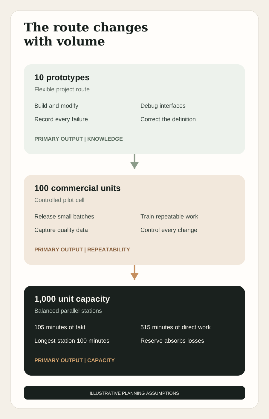
Capacity begins with demand and available production time. In the illustrative case, the plant plans one shift for 250 days per year with 420 net production minutes per day after breaks and planned meetings. One thousand accepted units therefore require an average takt time of 105 net minutes per unit. Takt is the demand pace, not the time required to build one rover.
The assumed route contains 515 minutes of direct work across kitting, structure, mobility, electrical integration, enclosure, programming, calibration, final test, and packing. That work can be divided among stations operating in parallel. The longest assumed station is final test at 100 minutes, which fits inside the 105 minute takt on paper. The line would have theoretical capacity for 1,000 units only if availability, yield, staffing, supply, and changeovers were perfect.
The planning model therefore targets about 1,190 attempted units before losses, then applies an illustrative 84 percent combined allowance for uptime, staffing variation, changeover, and accepted yield. That returns approximately 1,000 accepted units. This is arithmetic for teaching. A real capacity study would use measured cycle distributions, product mix, failure history, shift calendars, material availability, repair loops, maintenance, and simulation where interactions are complex.
Illustrative Capacity Calculation for 1,000 Units
Net annual time
Assumption
250 days times 420 minutes
Calculation
105,000 minutes
Meaning
Available scheduled production time after planned nonproduction periods
Required accepted output
Assumption
1,000 units
Calculation
105,000 divided by 1,000
Meaning
105 minutes of takt per accepted unit
Longest station
Assumption
100 minutes
Calculation
100 is less than 105
Meaning
The proposed balance fits takt before losses
Theoretical attempted output
Assumption
One unit every 105 minutes
Calculation
1,000 units
Meaning
No reserve exists if takt is used as the operating cycle
Planning cycle
Assumption
One attempted unit every 88 minutes
Calculation
105,000 divided by 88
Meaning
Approximately 1,193 attempted units before losses
Combined planning allowance
Assumption
84 percent accepted availability
Calculation
1,193 times 0.84
Meaning
Approximately 1,002 accepted units
| Planning Input | Assumption | Calculation | Meaning |
|---|---|---|---|
| Net annual time | 250 days times 420 minutes | 105,000 minutes | Available scheduled production time after planned nonproduction periods |
| Required accepted output | 1,000 units | 105,000 divided by 1,000 | 105 minutes of takt per accepted unit |
| Longest station | 100 minutes | 100 is less than 105 | The proposed balance fits takt before losses |
| Theoretical attempted output | One unit every 105 minutes | 1,000 units | No reserve exists if takt is used as the operating cycle |
| Planning cycle | One attempted unit every 88 minutes | 105,000 divided by 88 | Approximately 1,193 attempted units before losses |
| Combined planning allowance | 84 percent accepted availability | 1,193 times 0.84 | Approximately 1,002 accepted units |
The 84 percent factor is an explicit teaching assumption, not an industry benchmark. Availability and yield should be modeled separately with measured evidence in a real factory.
Illustrative Parallel Station Balance
Kitting and identity
Direct Work per Unit
35 minutes
Main Resource
Material handler and controlled inventory
Capacity Risk
Shortage, wrong revision, or unverified substitute
Structure assembly
Direct Work per Unit
75 minutes
Main Resource
Fixture, torque tools, and assembler
Capacity Risk
Datum shift, fit issue, or slow fastener access
Mobility assembly
Direct Work per Unit
60 minutes
Main Resource
Assembly fixture and functional tester
Capacity Risk
Alignment, encoder convention, or brake adjustment
Electrical integration
Direct Work per Unit
90 minutes
Main Resource
Electrical bench and technician
Capacity Risk
Harness routing, connector damage, or power fault
Enclosure and perception
Direct Work per Unit
45 minutes
Main Resource
Alignment tools and clean handling
Capacity Risk
Optical contamination, occlusion, or seal damage
Software and calibration
Direct Work per Unit
80 minutes
Main Resource
Controlled station, target, and operator
Capacity Risk
Network delay, wrong release, unstable fixture, or retry loop
Final test
Direct Work per Unit
100 minutes
Main Resource
Test area, course, charger, and operator supervision
Capacity Risk
Test congestion, false failure, repair return, or environmental variation
Pack and release
Direct Work per Unit
30 minutes
Main Resource
Packaging cell and final audit
Capacity Risk
Accessory, label, or battery shipment mismatch
| Station | Direct Work per Unit | Main Resource | Capacity Risk |
|---|---|---|---|
| Kitting and identity | 35 minutes | Material handler and controlled inventory | Shortage, wrong revision, or unverified substitute |
| Structure assembly | 75 minutes | Fixture, torque tools, and assembler | Datum shift, fit issue, or slow fastener access |
| Mobility assembly | 60 minutes | Assembly fixture and functional tester | Alignment, encoder convention, or brake adjustment |
| Electrical integration | 90 minutes | Electrical bench and technician | Harness routing, connector damage, or power fault |
| Enclosure and perception | 45 minutes | Alignment tools and clean handling | Optical contamination, occlusion, or seal damage |
| Software and calibration | 80 minutes | Controlled station, target, and operator | Network delay, wrong release, unstable fixture, or retry loop |
| Final test | 100 minutes | Test area, course, charger, and operator supervision | Test congestion, false failure, repair return, or environmental variation |
| Pack and release | 30 minutes | Packaging cell and final audit | Accessory, label, or battery shipment mismatch |
Total assumed direct work is 515 minutes, or about 8.6 hours per unit. Parallel stations allow throughput to differ from total labor content.
Cost Falls Only When the System Earns It
Higher volume can reduce purchased part prices, spread tooling and launch work, improve labor through fixtures and training, and lower rework through process control. It can also increase working capital, minimum order commitments, tooling exposure, field liability, and the cost of a design mistake. A lower quoted unit price does not guarantee a lower economic risk.
The following model makes its assumptions visible. It is not a quote, forecast, target margin, or estimate for a real rover. Purchased materials, supplier fabrication, labor rates, labor hours, quality loss, packaging, and launch investment are invented teaching inputs. The purpose is to show how a manufacturing team should structure the calculation and which exclusions can make an attractive unit number misleading.
Public component prices can anchor individual line items but cannot establish the finished bill. Raspberry Pi and Luxonis publish prices for selected compute and camera products. A manufacturer would still need the exact released variants, volume terms, carrier board, cables, thermal solution, duties, freight, inventory, incoming verification, integration, and lifecycle plan. Catalog price is evidence for one item on one date, not a product cost model.
Illustrative Unit Cost Model
Purchased components and materials
10 Prototypes
$4,800
100 Units
$3,600
1,000 Unit Capacity
$2,850
Outsourced fabrication and processing
10 Prototypes
$1,500
100 Units
$900
1,000 Unit Capacity
$650
Direct labor
10 Prototypes
$2,080 at 32 hours and $65 per hour
100 Units
$990 at 18 hours and $55 per hour
1,000 Unit Capacity
$387 at 8.6 hours and $45 per hour
Illustrative scrap and rework allowance
10 Prototypes
$756
100 Units
$270
1,000 Unit Capacity
$105
Packaging and inbound or outbound handling
10 Prototypes
$350
100 Units
$250
1,000 Unit Capacity
$180
Allocated development, tooling, fixtures, and launch
10 Prototypes
$3,000
100 Units
$1,200
1,000 Unit Capacity
$450
Illustrative planning total
10 Prototypes
$12,486
100 Units
$7,210
1,000 Unit Capacity
$4,622
| Cost Layer | 10 Prototypes | 100 Units | 1,000 Unit Capacity |
|---|---|---|---|
| Purchased components and materials | $4,800 | $3,600 | $2,850 |
| Outsourced fabrication and processing | $1,500 | $900 | $650 |
| Direct labor | $2,080 at 32 hours and $65 per hour | $990 at 18 hours and $55 per hour | $387 at 8.6 hours and $45 per hour |
| Illustrative scrap and rework allowance | $756 | $270 | $105 |
| Packaging and inbound or outbound handling | $350 | $250 | $180 |
| Allocated development, tooling, fixtures, and launch | $3,000 | $1,200 | $450 |
| Illustrative planning total | $12,486 | $7,210 | $4,622 |
Invented teaching case in United States dollars. Excludes company overhead, software development, certification, capital financing, warranty, service, sales, general administration, taxes, profit, and the cost of inventory timing. It must not be used as a market price or investment forecast.
Costs That a Bill of Materials Does Not Capture
Nonrecurring engineering
Why It Matters
Design, tooling, fixtures, programs, validation, supplier setup, and launch work occur before stable output
Working capital
Why It Matters
Material is often paid for before the customer pays for the finished rover
Minimum quantities
Why It Matters
The plant may buy more batteries, boards, connectors, packaging, or custom parts than near term demand consumes
Quality loss
Why It Matters
Inspection, repair, scrap, containment, line interruption, returns, and corrective action consume real capacity
Change exposure
Why It Matters
Inventory and tooling can become obsolete when the design changes
Warranty and service
Why It Matters
Field diagnosis, replacement parts, shipping, software support, and customer downtime continue after release
Capacity reserve
Why It Matters
A line planned at perfect utilization has no practical room for failures, training, demand variation, or maintenance
| Cost | Why It Matters |
|---|---|
| Nonrecurring engineering | Design, tooling, fixtures, programs, validation, supplier setup, and launch work occur before stable output |
| Working capital | Material is often paid for before the customer pays for the finished rover |
| Minimum quantities | The plant may buy more batteries, boards, connectors, packaging, or custom parts than near term demand consumes |
| Quality loss | Inspection, repair, scrap, containment, line interruption, returns, and corrective action consume real capacity |
| Change exposure | Inventory and tooling can become obsolete when the design changes |
| Warranty and service | Field diagnosis, replacement parts, shipping, software support, and customer downtime continue after release |
| Capacity reserve | A line planned at perfect utilization has no practical room for failures, training, demand variation, or maintenance |
Quality Must Follow the Product Through the Route
Final inspection cannot economically discover every hidden defect. Quality gates should sit where information is cheapest and corrective action is still possible. A harness is tested before installation. Power polarity is checked before sensitive electronics are connected. Sensor visibility is confirmed before the enclosure closes. Software identity is captured before calibration. The final test then confirms the integrated configuration.
IPC identifies separate expectations for printed boards, soldered assemblies, cable and wire harnesses, and design documentation. The correct standards and acceptance class depend on the actual product and contract. A startup should not copy a standard number into a drawing without understanding the requirements, supplier capability, inspection method, and commercial consequences.
For an industrial mobile platform, safety and compliance planning starts during architecture. UL Solutions notes that automated mobile platform evaluation can involve fire, shock, energy hazards, batteries, object detection, functional safety, payloads, and product integration. The applicable requirements depend on the product, market, use environment, and jurisdiction. Buying a listed component does not automatically certify the integrated rover.
A Layered Rover Quality Plan
Supplier approval
Typical Evidence
Capability review, sample, certificate scope, process evidence, commercial terms, and change notice agreement
Failure Response
Approve, conditionally approve with controls, develop another source, or redesign
Incoming control
Typical Evidence
Identity, condition, quantity, certificate, sample measurement, or functional screen based on risk
Failure Response
Quarantine the lot, notify supplier, contain affected inventory, and decide disposition
In process assembly
Typical Evidence
Fixture result, torque, continuity, polarity, clearance, image, software identity, and operator signoff
Failure Response
Stop at the station, correct if authorized, record rework, and investigate recurrence
Calibration
Typical Evidence
Station status, reference artifact, environmental condition, calculated parameters, and limit result
Failure Response
Prevent release, verify setup, repeat only under controlled rules, and retain original data
Final acceptance
Typical Evidence
Complete configuration, safety functions, operating mission, communications, charging, accessories, and audit
Failure Response
Hold the unit and any suspect population until scope and cause are understood
Field feedback
Typical Evidence
Unit history, symptom, environment, logs, returned hardware, and corrective action
Failure Response
Protect customers, contain affected configurations, correct product or process, and verify effectiveness
| Gate | Typical Evidence | Failure Response |
|---|---|---|
| Supplier approval | Capability review, sample, certificate scope, process evidence, commercial terms, and change notice agreement | Approve, conditionally approve with controls, develop another source, or redesign |
| Incoming control | Identity, condition, quantity, certificate, sample measurement, or functional screen based on risk | Quarantine the lot, notify supplier, contain affected inventory, and decide disposition |
| In process assembly | Fixture result, torque, continuity, polarity, clearance, image, software identity, and operator signoff | Stop at the station, correct if authorized, record rework, and investigate recurrence |
| Calibration | Station status, reference artifact, environmental condition, calculated parameters, and limit result | Prevent release, verify setup, repeat only under controlled rules, and retain original data |
| Final acceptance | Complete configuration, safety functions, operating mission, communications, charging, accessories, and audit | Hold the unit and any suspect population until scope and cause are understood |
| Field feedback | Unit history, symptom, environment, logs, returned hardware, and corrective action | Protect customers, contain affected configurations, correct product or process, and verify effectiveness |
Change Control Prevents Invisible Products
A physical AI product changes in hardware, software, models, data, calibration, and suppliers. A new perception model can alter operating behavior without changing one screw. A replacement camera can fit the same bracket while changing optics, timing, firmware, thermal load, or calibration. A new battery cell can preserve voltage and capacity while changing safety evidence and thermal behavior.
Every proposed change should identify the reason, affected items, compatibility, inventory disposition, tests required, documents updated, units receiving the change, and approval authority. The team also needs an effectivity rule: the change may begin at a named serial number, lot, work order, or service event. Without effectivity, the company knows the new design but not which product exists in the field.
Configuration control does not mean refusing to learn. It means making learning traceable. Engineers should be able to run controlled experiments and urgent corrective changes. Production and service should then know exactly which approved result applies to each unit.
One Change, Seven Questions
Why change?
Required Answer
Defect, cost, availability, performance, safety, compliance, service, or simplification
What changes?
Required Answer
Part, drawing, supplier, process, tool, software, model, calibration, label, test, or documentation
What else is affected?
Required Answer
Interfaces, inventory, fixtures, service parts, training, certifications, customer commitments, and data
How is it verified and validated?
Required Answer
Analysis, inspection, test, demonstration, regression coverage, and realistic use
Who approves it?
Required Answer
Named technical, quality, operations, safety, commercial, and release authorities as appropriate
When does it begin?
Required Answer
Defined serial, lot, order, date, software release, or retrofit campaign
How is history preserved?
Required Answer
Old and new baselines, decision record, results, deviations, and affected unit list
| Question | Required Answer |
|---|---|
| Why change? | Defect, cost, availability, performance, safety, compliance, service, or simplification |
| What changes? | Part, drawing, supplier, process, tool, software, model, calibration, label, test, or documentation |
| What else is affected? | Interfaces, inventory, fixtures, service parts, training, certifications, customer commitments, and data |
| How is it verified and validated? | Analysis, inspection, test, demonstration, regression coverage, and realistic use |
| Who approves it? | Named technical, quality, operations, safety, commercial, and release authorities as appropriate |
| When does it begin? | Defined serial, lot, order, date, software release, or retrofit campaign |
| How is history preserved? | Old and new baselines, decision record, results, deviations, and affected unit list |
Physical AI Can Accelerate the Work Without Owning the Baseline
AI tools can help engineers compare requirements with drawings, summarize supplier documents, flag bill of materials gaps, generate draft work instructions, classify defects, search historical failures, propose inspection plans, and analyze cycle data. Vision models can support assembly verification. Simulation and generated test cases can expose interface assumptions before hardware is cut.
The useful boundary is assistance with evidence and decisions, not unreviewed authority over the product. A generated work instruction may omit a safety step. A supplier match may confuse similar part numbers. A vision classifier may fail on a rare defect or new lighting condition. A language model may produce a plausible but nonexistent specification. Released manufacturing data still needs accountable owners, controlled sources, verification, permissions, and change history.
Physical AI also changes the product being manufactured. The rover leaves the line with sensors, compute, models, software, and calibration that determine its actions. Manufacturing must therefore prove both physical construction and configured behavior. The product is not complete when the hardware looks right. It is complete when the approved hardware and software configuration performs safely within the intended operating boundary.
AI Assistance Across Product Realization
Design review
Potential Use
Compare requirements, interfaces, drawings, and prior failures for missing questions
Required Control
Engineer review against controlled source data and real process capability
Sourcing
Potential Use
Normalize supplier descriptions and identify candidate alternates
Required Control
Exact manufacturer data, authorized source, qualification, and approved substitution
Work instructions
Potential Use
Create a first draft from models, routes, and build notes
Required Control
Operator trial, safety review, revision control, and verified images
Quality inspection
Potential Use
Detect visible presence, orientation, damage, or process patterns
Required Control
Representative data, controlled imaging, uncertainty handling, monitoring, and human escalation
Production planning
Potential Use
Explore line balances, shortages, schedules, and what if scenarios
Required Control
Validated inputs, transparent assumptions, constraint review, and controlled release to operations
Failure analysis
Potential Use
Connect logs, test data, unit history, and similar defects
Required Control
Data integrity, privacy, engineering diagnosis, and verification of corrective action
| Task | Potential Use | Required Control |
|---|---|---|
| Design review | Compare requirements, interfaces, drawings, and prior failures for missing questions | Engineer review against controlled source data and real process capability |
| Sourcing | Normalize supplier descriptions and identify candidate alternates | Exact manufacturer data, authorized source, qualification, and approved substitution |
| Work instructions | Create a first draft from models, routes, and build notes | Operator trial, safety review, revision control, and verified images |
| Quality inspection | Detect visible presence, orientation, damage, or process patterns | Representative data, controlled imaging, uncertainty handling, monitoring, and human escalation |
| Production planning | Explore line balances, shortages, schedules, and what if scenarios | Validated inputs, transparent assumptions, constraint review, and controlled release to operations |
| Failure analysis | Connect logs, test data, unit history, and similar defects | Data integrity, privacy, engineering diagnosis, and verification of corrective action |
Seven Beginner Mistakes From Prototype to Production
The first mistake is treating the prototype bill as a production bill. Development boards, hand modified parts, substitute connectors, temporary cables, and engineer knowledge can prove a concept without defining a repeatable product. The second is ordering long lead material before interfaces and change exposure are understood.
The third mistake is optimizing purchase price while ignoring tooling, freight, inspection, failures, inventory, and supplier response. The fourth is automating an unstable sequence. Automation repeats ambiguity quickly. The fifth is waiting until final test to discover hidden assembly defects.
The sixth mistake is freezing hardware while allowing software, models, and calibration to change without equivalent configuration discipline. The seventh is confusing one hundred completed units with a capable process. Output becomes evidence only when the team knows the configuration, attempted quantity, accepted quantity, defect pattern, rework, cycle distribution, downtime, and field result.
Your Product Manufacturing Checkpoint
You should now be able to start with a product architecture, turn it into a controlled bill of materials, connect each item to a make or buy decision, and place every transformation on a production route. You should also be able to distinguish total labor content from takt, a catalog price from finished product cost, and a passing component from a validated integrated rover.
The central idea is simple. A product becomes manufacturable when its design, supply chain, process, quality evidence, software, and change history describe the same approved thing. Volume does not create that discipline. Volume exposes whether it exists.
Five Questions You Should Now Be Able to Answer
What exactly is the product?
What a Good Answer Contains
Requirements, product structure, revisions, software, calibration, labels, packaging, and accepted configuration
What must be made and bought?
What a Good Answer Contains
Structured bill, approved sources, process ownership, interfaces, lead time, and qualification evidence
How does one unit move through production?
What a Good Answer Contains
Ordered operations, resources, instructions, quality gates, records, repair loops, and release authority
Can the route meet demand?
What a Good Answer Contains
Net time, takt, measured cycles, parallel work, constraint, availability, yield, staffing, material, and reserve
How will the company know what changed?
What a Good Answer Contains
Controlled baseline, review, effectivity, validation, inventory decision, and unit history
| Question | What a Good Answer Contains |
|---|---|
| What exactly is the product? | Requirements, product structure, revisions, software, calibration, labels, packaging, and accepted configuration |
| What must be made and bought? | Structured bill, approved sources, process ownership, interfaces, lead time, and qualification evidence |
| How does one unit move through production? | Ordered operations, resources, instructions, quality gates, records, repair loops, and release authority |
| Can the route meet demand? | Net time, takt, measured cycles, parallel work, constraint, availability, yield, staffing, material, and reserve |
| How will the company know what changed? | Controlled baseline, review, effectivity, validation, inventory decision, and unit history |
Next in the Series
Part 4 will move beyond the rover and map the industrial ecosystem that makes production possible. We will separate equipment manufacturers, component suppliers, automation platforms, machine builders, distributors, systems integrators, contract manufacturers, engineering firms, contractors, and software providers.
One robot machine tending cell will show who supplies the arm, tooling, safety, controls, vision, fixture, machine interface, programming, installation, acceptance, and ongoing service. The goal is to understand not only what a factory needs, but which kind of company is responsible for delivering each layer.
Research Method
This report uses NIST digital thread research for the connection among product design, manufacturing, measurement, and lifecycle information. NASA systems engineering guidance supplies the general distinctions among configuration management, product realization, verification, and validation. These practices are adapted as educational manufacturing principles and do not imply that the hypothetical rover follows a NASA program standard.
IPC materials provide the electronics design, documentation, assembly, cable harness, and acceptance context. ASQ provides the definitions of takt time, cycle time, process capability, and standard work. UL Solutions provides general context on the safety evaluation topics that can apply to industrial automated mobile platforms.
Raspberry Pi and Luxonis are representative public component examples. Their specifications, availability statements, and listed prices were accessed September 16, 2026. Maxon is included as a representative robotics motion supplier. No named company is claimed to supply the hypothetical rover, approve this architecture, or validate the illustrative production plan.
Every rover specification, supplier choice, labor time, cost, yield, route, and capacity number in this report is an explicit hypothetical teaching assumption. The material is educational. A real product requires qualified engineering, safety, quality, compliance, cybersecurity, commercial, and legal review for its intended markets and use environments.
Continue the series
Inside the Physical AI FactoryPart 3 of 8

About the author
Rodolfo Garcia Calderoni, CFA
Rodolfo is the founder of Black Scarab, where he covers the technologies and commercial signals shaping physical AI adoption.
Meet RodolfoBlack Scarab Weekly
Catch up on physical AI in one email
Every new Black Scarab deep dive and news report, collected into one clear Thursday briefing.
Related Insights
Manufacturing
Types of Manufacturing Machines: A Beginner's Guide to Factory Equipment
A visual machine atlas covering how factory equipment removes, forms, adds, molds, casts, joins, assembles, inspects, moves, and packages material.
Read related insight
Manufacturing
Learn to See a Factory: What Every Room, Process, and Production Flow Actually Does
A practical tour of the modern manufacturing plant, from receiving and fabrication to assembly, quality, shipping, maintenance, and the production flows that connect them.
Read related insight
Manufacturing
How Modern Manufacturing Works: A Beginner's Guide to Factories and Physical AI
A first principles map of the modern factory, from materials, machines, and production flow to automation, industrial software, company roles, and the emerging place of physical AI.
Read related insight
Next Step
Explore a commercial opportunity in Mexico
If you are exploring how a physical AI technology could fit the Mexican market, Black Scarab can help assess the opportunity, map relevant stakeholders, and define a credible commercial next step.